This calculation was performed for verification of a simple analytical relation (established here) for the force acting on a frromagnetic from a winding. Here is this equation:
| F = Bsat · (H2 - H1)·S | (1) |
where Bsat is saturation flux density of the material, S - core cross section in a plane perpendicular to the solenoid's axis, H1,2 - field intensity (in absence of a core) at the points corresponding to the intersection of the rear and front edges of the projectile with the axis. This formula should work good in a strong filed when the ferromagnetic is deeply saturated.
For the verification, I used simulation in FEMM for a model of the system with a coil constructed using the program's built-in graphical editor. To determine the force acting on the projectile (core), I used integration using the Integrate->Force via Weighted Stress Tenzor function. To do this, activate the menu item Operate->Areas in the results analysis window, select the space corresponding to the core volume (it will turn green), and select the type of calculated value in The integrate menu (see figure 1).
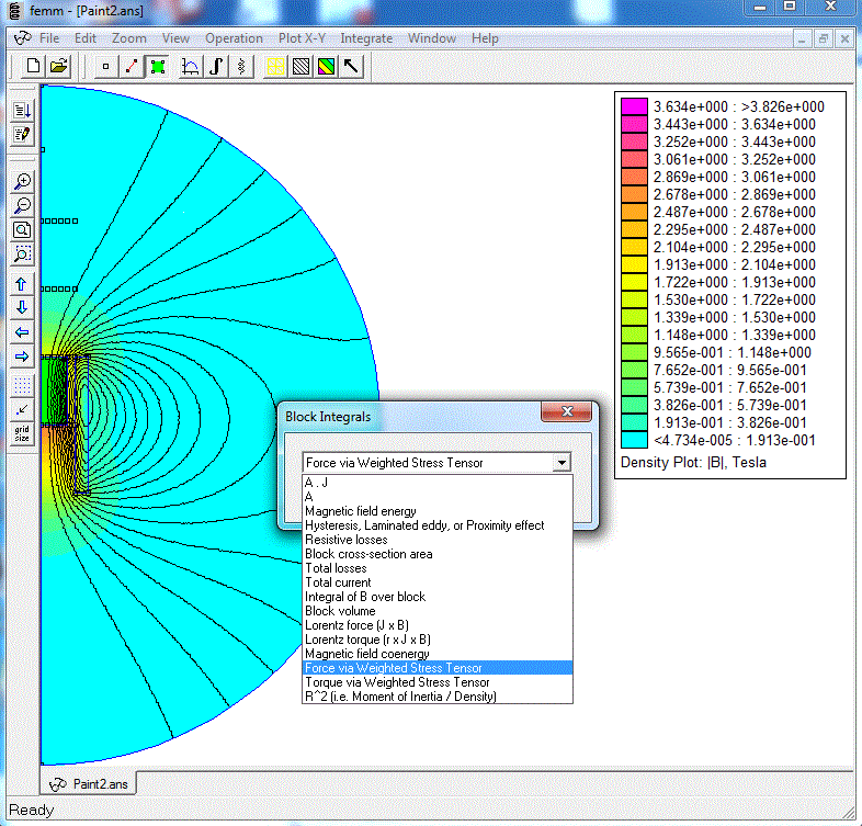 |
Fig. 1. Calculation of the force on the core with FEMM. |
Modeling was performed for 3 types of coils which parameters are below:
| Parameter/coil type | Type 1 ("thin") | Type 2 ("mean") | Type 3 ("thick") |
| Inner dia, mm | 10 | 10 | 10 |
| Length, mm | 20 | 20 | 20 |
| Outer dia, mm | 14 | 20 | 40 |
| Wire gauge (dia of copper core) | AWG24 (0,51 mm) | AWG24 (0,51 mm) | AWG24 (0,51 mm) |
| Fill-factor by a dia, a | 0,9217 | 0,9217 | 0,9217 |
| Turns | 130 | 324 | 977 |
| Resistance, Ohm | 0,42 | 1,31 | 6,56 |
| Current, A | 310 | 100 | 19,8 |
Table 1. Parameters of the analyzed coils.
Cylindrical rods were used as projectiles, made of material No. 154. This is a ferromagnetic material with a special shape of the B(H) dependence curve, which best corresponds to the experimental data of various coilguns, and, in addition, contains points in the region of very strong fields inherent for the devices under consideration (data on original materials from the FEMM library are not available in these areas). By the way, a lot of work was done on the Arsenal forum to establish the properties of this "model" metal, which can be found here (in Russian only).
The length of these cylinders ranged from 10 mm to 30 mm, the coordinates of the front face - from 10 mm (in our model this corresponds to a winding center) to 30 mm, and the rear faces - from 20 mm (the line coincides with the end of the coil - this is the case shown in Fig. 1) up to 40 mm. I did not calculate the longer rods, because in that case their back end would be too close to the boundary of the modeling area, and there are concerns about the validity of the boundary conditions used.
The procedure for verifying formula (1) is as follows.
First, for the models described in table 1, the value of the field strength H is calculated at points located on the axis of each coil at distances of 10, 20, 30 and 40 mm from its center. Then, ferromagnetic cores are introduced into the system and the force F of their attraction to the winding is determined using the procedure described above. At the last step, the saturation induction value is calculated using the formula (1), based on the found values of the stresses and forces, as well as with a known cross-sectional area of the core.
The criterion for the truth of the relation (1) could be the fact that the value of Bsat , estimated in this way, would take in all the analyzed cases an identical value, close to 2 T. Indeed, as described on the corresponding page of the Arsenal Forum, the B(H) curve for material 154 is derived from the assumption that in strong fields, the curves (more precisely, already lines) of the magnetization of air and this ferromagnet should run parallel with a shift of 2 Tesla (see figure 2). Thus, having obtained the same value using the estimated ratio (1), we would confirm its validity.
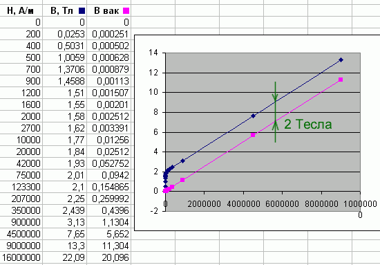 |
Fig. 2. Magnetization curve of №154 material (taken from Arsenal Forum). |
Let's see what happens in reality.
Fig. 3, 4 and 5 show the dependence of estimated values of Bsat , obtained by this way, from the difference of intensities at the front and rear faces of the projectile (dH = H2-H1), from the mean value of H (Hmean = (H2+H1)/2) at the ends, and from the field on the front face (H2), respectively.
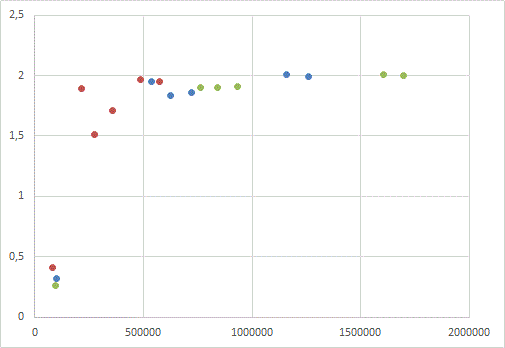 |
Fig. 3. Вsat (dH) dependence of the calculated saturation flux density of the core from a field gradient between its edges. Green points - "thin" coil, blue - "mean" one, red - "thick" coil (see Table. 1).
|
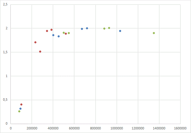 |
Fig. 4. Вsat (Hmean) dependence of the calculated saturation flux density of the core from a mean field on its edges. Green points - "thin" coil, blue - "mean" one, red - "thick" coil (see Table. 1).
|
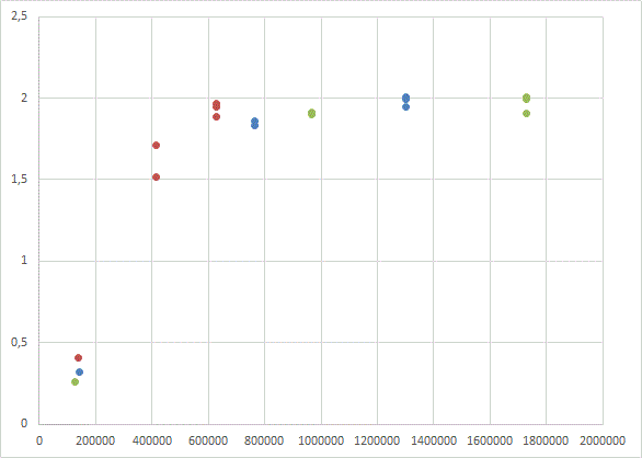 |
Fig. 5. Вsat (H2) dependence of the calculated saturation flux density of the core from a field on its front end. Green points - "thin" coil, blue - "mean" one, red - "thick" coil (see Table. 1). |
It is clearly seen that for strong fields all values are grouped around the expected induction value of 2 T, regardless of the method of plotting.
As for the" tails "of dependencies for small fields (they correspond to completely" non-physical " values of Bsat less than 0.5 T), the following can be noticed here. The lower the field strength, the weaker the force acting on the projectile. Thus, a point with a minimum calculated value of Bsat 0,26 Tesla (it is obtained for the "thin" winding and 10 mm long projectile located between 20 and 30 mm from the center of the coil) corresponds to a retracting force of only 1,9 Newtons. If we assume that this force acts on an iron projectile with the specified parameters across the acceleration length of 0,5 m (this is probably the longest length for a multi-stage portable accelerator, since in addition to the coils, some sensors and other structural elements must be placed on its barrel), then it can acquire a speed of only..17,5 m / s. It is obvious that this case does not suit us at all - it is reasonable to expect speeds of at least 80..100 m/s from such a coilgun, and such speeds just require fields over 500 kA/m, at which all the values on the graphs are already "collected" to the same 2 T.
Thus, for coil accelerators of ferromagnets (in the ranges of fields that we are interested in as gauss-builders), formula (1) can be considered proven.