| Home » Articles » Theoretical papers » Coilgun calculations |
The main difficulty in constructing high-efficiency multistage accelerators is a huge laboriousness of this process. One of solutions could be to make all accelerating stages (including electronics and winding itself) identical - it would allow a high degree of unification which in turn could hasten all the construction process. This and this species are examples of such approach. But a probem arises here. In conventional coilgun constructing, a tricky process of adjustment of geometrical parameters of each coil is conducted (with a help of FEMM, for example) to achieve the best performance of the windings. As a rule, one gets a system with decreasing coil diameter to the end of a burrel. For instance, we can examine EM-3 ("Electric bow") situation. The latter coilgun shows that we can get approximately the same peak current by tunning the caps for each stage - this allows the same power switches to be utilized, but the geometry variation is unavoidable. Trying to save a time and using identical coils, we get substantially lower efficiency. If a common capacitor is used, the situation is even worse because the cap would try to keep the same forms of current in all stages which is far from optimal conditions for acceleration. However, the common-capacitor sytem with identical coils looks so attractive that I tried to assess the limits of its application without any complicated calculations. The resuls are below.
1. General suggestions. At first, let us remind the waveforms for current in RLC-circuit:
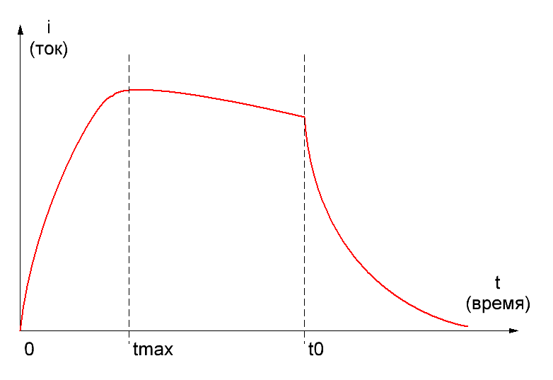
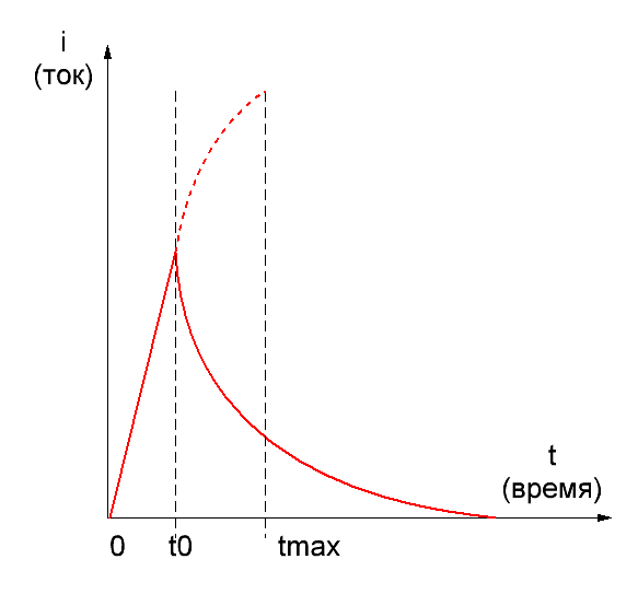
Fig. 1. Current in RLC coilgun circuit with a closeable power switch. Moments according to the peak current and switch turn-off are marked.
As we see, the current rises and reaches its maximum at the moment tmax, and then starts to decay. When the projectile is completely pulled into the coil (this time is suggested as t0), we have to switch the current off to avoid suck-back effect. Then, it decreases according to different laws in dependence on a damping scheme applied in the circuit.
Remarks: 1) Fig.1 demonstrates an exponential decay typical for a simple diode+resistor damping circuit. As the form depends on the specific circuit applied, we shall not consider it further. 2) Theory and practice show that the length of a projectile equal to the length of a coil is the most effective. That is what will be assumed below by default.
Suggesting the length and inside diameter (caliber) of the coil to be fixed, and the moments of the current inset (t = 0) and switch-off (t = t0) corresponding to the projectile ('s front end) entering the coil, and being completely pulled into it, the optimization of the system deduces to variation of outside diameter of the coil and wire gauge. Like shown here, these geometrical parameters fully determines the waveforms (provided the capacitance and its initial voltage, i.e.total energy, is fixed). Secondly, an accelerating froce acting on the projectile is proportional to the magnetic field i.e. ampere-turns: H ~ n·i (where n is turns per unit length of a coil). That coilgun which provides maximum force in all positions with minimum ohmic losses, would be the most effiicent. Thus, the optimization of the system can be described as selection of such geometric parameters of the coil that give an optimal pulse shape ensuring the force profile which corresponds best to each position of the projectile.
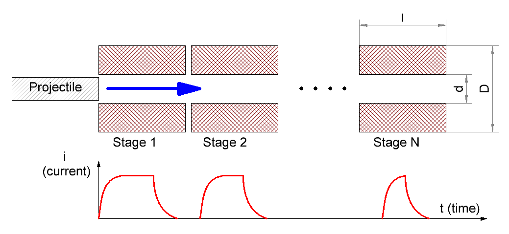
2. Problem formulation. The discourse articulated above is, in general, obvious and concerns a common case of multistage accelerator where it is possible to vary geometry of the accelerating coil and wire gauge (like gauss-builders do in many situations). Getting down to our "unified" system, we can conclude that its optimization reduces to the choice of geometry of (unitary) coil which provides the best efficiency throughout all the distance of acceleration. How can we choose it? Let's look at fig.1 again. If all the parameters of RLC-circuit are set, then pulse shape (including tmax duration) is fixed. For different stages, t0 changes only, which is connected with continuous acceleration of a projectile. This situation is illustrated on fig. 2, where oscillograms of current are shown for all stages basing on assumption of a very large common capacitor (which is close to our case). It is described here that current decays monotonically in such systems (AKA "overdamped").
Fig. 2. A sketch of multistage system with identical coils.
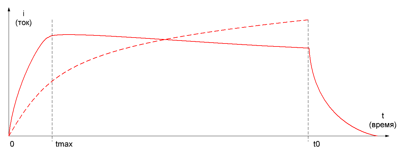
The question is how long the pulse can be until a substantial efficiency of acceleration preserves? Two limiting situations may be distinguised (fig. 3): 1) The projectile moves so fastly that current hasn't time to reach its maximum (t0<<tmax). Current slope is nearly linear here with tangent U/L (U - initial cap voltage, L - inductance); 2) The projectile moves so slowly that current has overcome its maximum long before t0 and is being on a study of free decay with ~ RC constant when the moment of t0 happens.
Fig. 3. Current forms for 2 limiting cases: very fast (left) and very slow (right) projectile movement. A graph for more optimal coil is also shown on the right picture with dashed line.
It is obvious that the acceleration efficiency is minimal in both cases. Let's try to prove it without any complicated computations. In the first situation it follows from the simple fact that further current increase could supply much higher velocity to the projectile, but we just "don't give it a chance" to do it. Thus, the coil is used ineffectively. In the second situation we can imagine a thicker coil containing more turns of wire of higher caliber, in such a way that the moment of current maximum is closer to switch-off (this hypothetical case is shown with a dashed line on the right of fig. 3). Charge consumed from a cap is nearly the same for both coils (it is clear because a square under the curves is close to identical), but the force would be stronger for the hicker one (because it contains more ampere-turns at the same current). Thus, the thicker coil would be more effective. So, we can expect that the most optimal coil must allow the current to achieve its peak but not to decrease substantially until the moment when a switch is closed. These speculations are validated by FEMM modelling, which demonstrates that the optimal range for t0 is: tmax<t0<4tmax (1) So, out task is to choose a form of a coil ensuring relation (1) in a range of velocities v for which an accelerator is designed. Provided coil form is fixed, an inverse problem may be stated: we want to assess maximum projectile speed which keeps a satisfactory efficiency of acceleration (as (1) says it makes vmax≈ l/t0, where l is length of the coil). That's what we are most interested in.
3. Solution. For the beginning, we can express tmax through the other parameters of the system. As it is shown here, in a strongly overdamped circuit
where
R,L,C - resistance, inductance and capacitance, correspondingly. The inductive constant (as shown here) may be expressed by geometrical parameters of the coil:
where a is density factor of the winding (i.e. relation of the wire core's diameter to its diameter in an isoltation, usually a ≈ 0,85), d and D - inner (caliber) and outer diameters of the coil, p - resistivity (1,75·10-6 Ohm·cm for copper). To express k coefficient we must find the cap constant This can be done as following. The capacitance through the energy conserved in a capacitor and initial voltage is 2E/U02. If a common capacitor is used to feed a coilgun, it can't be expended completely by a shot, because the last stages would be fed from nearly empty storage and wouldn't be able to accelerate a projectile considerably. Thus, some residual voltage must stay in the cap, which reasonable value may be Uf ≈ 3/4U0 - about half of the energy is spent in this case. So, the capacitance would be C≈4Ew/U02 (where Ew is the energy spent per one shot), and the capacitive constant is RC/2 ≈ 2Ew(R/U02). It's easy to note that the relation in the right part of this formula is an inverse ohmic power. In our situation current in gauss-gun during nearly all process of acceleration is limited by ohmic resistance, and acceleration efficiency is rather small, so we can say with good precision that ohmic power equals to total power Pw consumed from the capacitor, and
where tacc is total time of acceleration. Let us note this interesting fact: the capacitive constant of each coil in a strongly overdamped mulistage accelerator with common capacitance makes twice the aceeleration time. Expression (4) can be further modified if we remember that for a unformly accelerated motion (which is close to truth in our constant current-mode coilgun) mean velocity is half of the output one, so
where ls ls total length of acceleration. At last, ls can be assessed from equation (1) which tells that substantial efficiency is kept if a duration of movement of projectile through the first and the last stages differ in no more than 4 times. Hence, assuming unformly accelerated motion again, we get that maximum number of stages is 42=16. If more, either the first of them would have a weak influence on projectile (especially in comparison to hypothetical more optimal coils, see a right part of fig. 3), or the last ones would accelerate the shell only slightly (because the current couldn't reach a considerable value in them). So, ls≈16·l, and we can write finally:
Thus, we expressed the capacitive constant through the individual coil's length and maximum speed.
Remark: one can note that the equations (4)-(6) are deduced with some "voluntaristic" assumptions and contain values which can vary for dozens %s depending on a specific accelerator construction. But formula (2) says that the cap constant (included in k coefficient as denominator) is under a natural logarithm, which is known to depend only slightly on its argunent (in contrast to a linear dependence, for example).Thus, all those inaccuracies should't interfere our further calculations seriously.
Combining (1), (2), (3) and (6), we get for vmax :
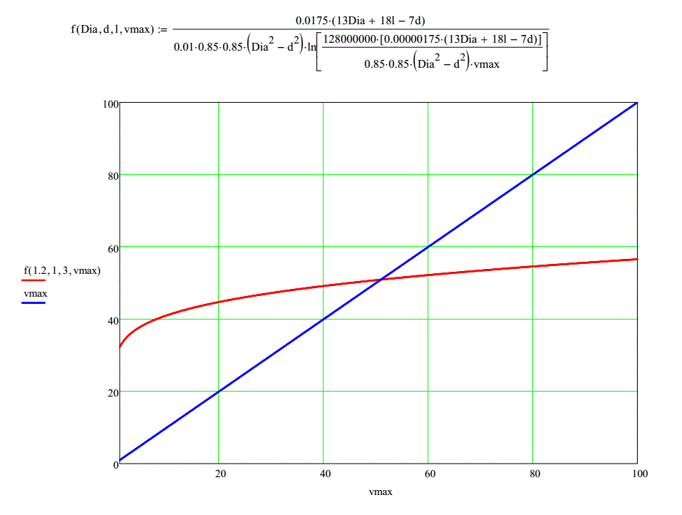
Having this, we can assess maximum speed on a basis of geometry of a coil. As we see, the value subject to assessment stands both in the left and right and part of the equation under the logarythm. Such relations in mathematics are called "transcendent" - they don't have exact analytical solution and are usually resolved graphically. Fig. 4 shows an example of such a solution for a system with following parameters: D =1,2 cm, d = 1 cm, l = 3 cm - the root is found as crosspoint of two dependences in MathCad.Other parameters are: a = 0,85, p= 1,75·10-6 Ohm·cm (it means copper wire). Equation (7) is defined accounting for the dimensions of its arguments here.
Fig. 4. Assessment of maximal velocity graphically.
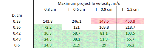
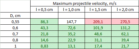
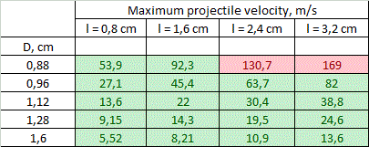
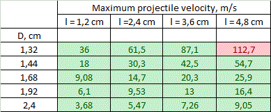
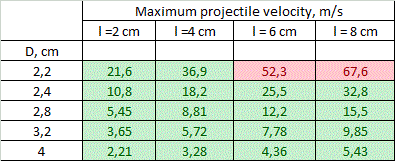
Tables of solution of (7) for vmax for different calibers d are resolved in fig. 5. The range of lengths of a coil is in the limits from l = d to l = 4·d (longer coils are ineffective according to FEMM modelling and lot of experimental data), and outer diameters are from D = 1,1·d to D = 2·d.
Coloration of some cells will be explained further. We can see that theoretical values of vmax range from unities to hundreds of meters per second, while the maximal values are obtained for smaller calibers. A critical clause must be made here: the values above are assessed theoretically basing only on geometrical parameters of a system. If an accelerator has a geometry shown in fig. 5 - this fact alone doesn't mean that velocity of its projectile will amout corresponding vmax. This only shows that the speed can be close to those theoretical limits - more realistic estimations may be obtained by modelling of the specific system in special programs like FEMM.
4. Limitations. Viewing the results in fig. 5, one can naturally ask: why such high speeds are not obtained in practice? Indeed, a lot of accelerators was built in gauge ranges 5...8 mm and none of them has had vmax more than 130 m/s till this moment (while majority of them utilize coils attenuated for different stages). This question can be answered taking into account natural limitations layed by physical laws and modern level of development of electronic components. Let us consider two of them only. 1) Coil heating. As an ohmic energy deposition occurs in a very short time duration, we can assume thermoexchange to be negligible (such processes are called "adiabatic" in physics). Thus, a final temperature is proportional to mass of a coil, and the shortest and thinnest coils of the smallest calibers are expected to be mostly heated. A calculation of the peak temperature was conducted for the coils with parameters depicted in fig. 5, accounting for the heat capacity of copper 0,4 J/(g·°C) and acceleration efficiency to be ≈ 8% for 8 mm dia and proportional to the caliber (which coincides to results of FEMM modelling). Then, a limit was suggested to be exceeded if the temperature rose higher than 300 °C - this is a point when heat-resistant electrical varnish loses its isolating abilities. As a strong tension occurs in a winding during a shot, the short circuit is expected in such situation. Moreover, in worst cases (according to right higher corners of the tables), melting point of copper is surpassed. As result, a range of geometrical characteristics of the coils for each caliber shrinks to band colored by green in fig. 5.
Remark: the calculation assumed only the first stages of the systems. It is easy to demonstrate that the uniformly accelerated projectile moving through 16 stages under constant current produces ohmic heat of approximately Ew/6,67 in the first one (the rest of them dissipates the energy decreasing as square root of its number). Initial temperture was suggested 25ºC.
2) Weight of the power capacitor. State-of-art electrolitic capacitors have some boundary energy accumulated per unit of mass, which varies depending on a specific type of a cap, and makes about 3 grams per Joule. Thus the maximum energy spent per shot is about 1000 J (this corresponds to total accumulated energy 2 kJ and capacitor mass of 6 kg - clearly close to a limiting value for a portable system). Comparing this number to the projectile muzzle energy corresponding to vmax from fig. 5, and taking into account a priori efficiencies mentioned above, we can get a range of velocities in which the energy capacitance of the system doesn't exceed those limits. This crossing would obviously take place for long heavy projectiles having maximum velocity. These "exorbitant" values are marked red in fig. 5. They correspond to situations when vmax can be achieved in stationary systems only (unless it doesn't contradict to the previous section about heat dissipation). Generally, we can see that both limits under concern work in one direction, constraining vmax for accelerators with thin long windings. "Heat" limit plays major role for the small calibers. At 8 mm bore the borders for the limits coincide, and for 12 and 20 mm bores "green zone" covers all the tables, and only "mass limit" manifests.
Other limiting factors like wight of the coils can also be taken into account by a similar way.
5. Conclusions and discussion. Following conclusions can be made from the results of fig. 5. 1) On the assumption of the geometrical properties of multistage accelerators with identical coils, theoretical velocities of 100..130 m/s are achievable for the calibers of less than 8 mm. The highest-speed caliber is about 5 mm. 2) The obstacles on the way to higher speeds are overheat of the coils for small-bore coilguns, and huge mass of the power capacitor for large-bore ones. For 20 mm and larger calibers velocities of more than 70 m/s cannot be obtained exclusively because of geometry of the coils (even without the "weight" limitation). 3) vmax falls with coil's thickness growth and length decrease. The thickness is more critical - the velocity decreases by an order of magnitude when the outer diameter grows from 1,1·d to 2·d, and only triply when relative length increases from d to 4·d.
It is clear that small calibers are the most attractive for breakthrough to high velocities. They are even more tempting if we note that mass is not the only reason which limits us in a portable system - the length acts, too. 16 stages of 12 mm gaussgun with l/d = 4 ratio would make 80..90 cm in total (assuming some additional place for detectors and other elements of the construction) - this is a bit excessively. For 3 mm-bore coilgun total length would be 20..30 cm only. The first table of fig. 5 says that supersonic velocities can be obtained theoretically. Сooling of windings with liquid nitrogen or Peltier modules can be used prior to shot to prevent overheat (such a method was proposed by many authors for induction launchers). In this case, the efficiency would increase not only because of active resistance reduction, but also because of the speed growth (see here). As for large caliber coilguns (more 10 mm) with identical windings, the results above make us claim that velocities of projectile of more than 100 m/s cannot be obtained with state-of-art electronics (unless some tricky technologies are utilized like recuperation).
Best regards, Yours Eugen.
| |||||||||||||||
| Views: 917 | | |||||||||||||||
| Total comments: 0 | |

 capacitive constant
 inductive constant
 damping factor


