| Home » Articles » Experiments » Other |
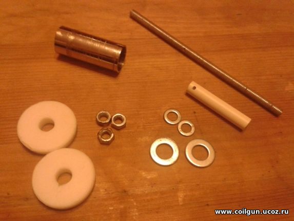
Main part of an electromagnetic launcher is a coil, which is usually impregnated with some fixing compounds like epoxy to avoid deformation during a shot. There are 2 ways to manufacture such coil: separately (on a suitable core), or directly on the bore of coilgun. The first one has an advantage, because there is no rigid connection to the bore, and the coil being unsatisfactory can be removed easily. I used direct winding in my earlier projects EM-2 and EM-3, but decided to perform something new in EM-4, so the special device (fixture) was produced (see below). All dimensions are for EM-4-fitted coils (length 16 mm, inside diameter 7 mm, outside diameter 15-25 mm). They must be varied for other coils. Well, the source materials for the fixture are: screw stud M5, short plastic tube (dia 7 mm out, >5 mm in), long metal tube 15 mm out dia, 3 M5 nuts, 2 M5 washers, 2 M10 washers and two teflon washers with outside diameter more than that of winding (I took 32 mm).
Fig. 1. Source materials for the fixture.
All the components are easily accessible in hardware stores. The tube cuts are best to be made by lathe, but I used easier way - a drill. Teflon washers are manuactured of 6 mm sheet with bimetall (composite) bit. Theoretically, they may have any form (not strictly annular), so one can saw them out with fretsaw, but round looks better, I think. Axial slot is made inside one of the washers ( with the help of needle file), and 5 mm cut is made in metal tube - this is done to draw out the wire of the first layer of the coil (see below). Besides, in 5 mm from the edge of the plastic tube and in about 2/3 length of the stud, thin hole must be drilled (I used 2 mm dia). All that stuff is assembled like shown in fig. 2.
Fig. 2. Schematic picture of the winding assembly.
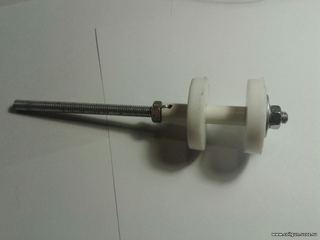
One can see that the rod is longer than all other details - that is in order to leave enough space to use camps of winding machine. The procedure looks like follows: 1) The device is completely assembled except for long metal tube. A thin metal object is inserted into the hole (it may be a piece of wire, little nail or straightened clip) to fix the plastic tube (fig. 3).
Fig. 3. Assembled device.
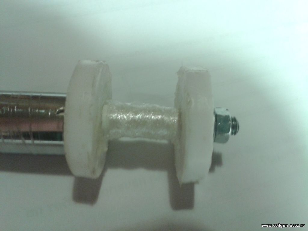
2) The place for coil is wound by few turns of thin polyethylene film ( I used food wrapping film or packet for sandwich, cut to appropriate pieces). It is necessary to ensure ease removal of the wound coil from the core (fig. 4).
Fig. 4. Tape wrapping.
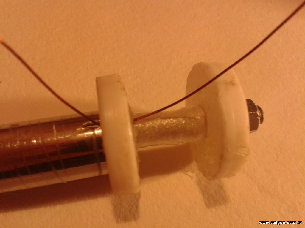
3) One end of the wire is passed through the slot of the washer from the side intended for winding, than through the cut in metal tube, and the tube is fixed on rod (fig. 5). Free piece of the wire should be made quite long - any excess may be cut out later.
Fig. 5. Preparation of the wire.
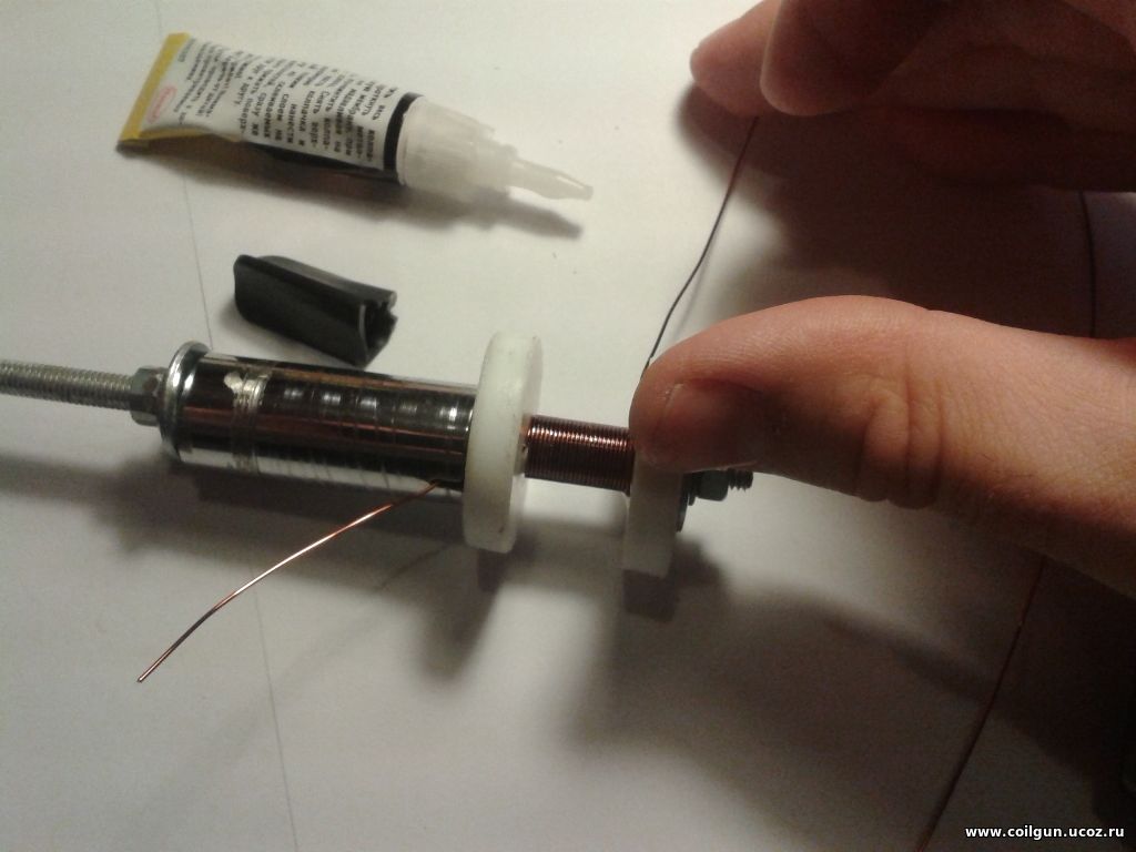
4) The first layer is wound with some pull (fig..6). It must be layed turn-to-turn and soaked with super-glue immediately.
Fig. 6. 1st layer winding.
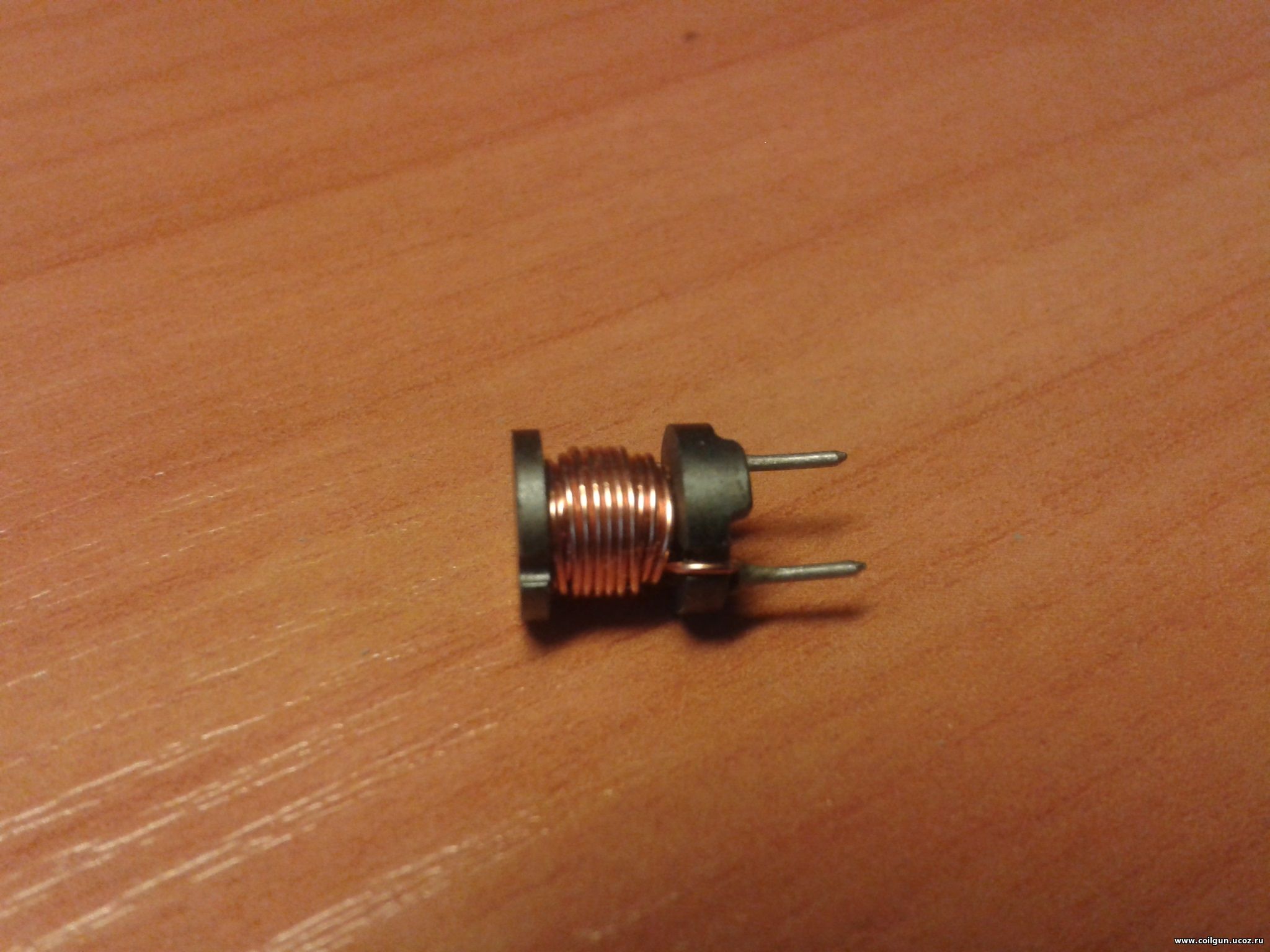
5) Then, the rest of the coil is wound soaking with epoxy after each 2-3 layer. In particular, attention should be paid to the ends of it, as there are never integer number of turns along a layer, so defects are created there. That's why we see successively decreasing numer of turns in industrial-produced coils (fig. 7).
Fig. 7. 47 microHn drossel by Sumida. One can see decreasing turns in each next layer.
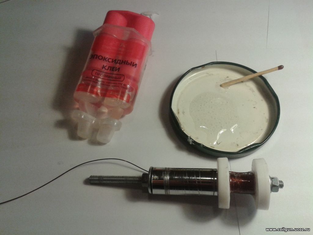
But we shoul get rectangular (in cross section) winding. The solution is simple - I just don't wind last 1-2 turns in each 2nd-3d layer and use epoxy to fill the cavity. The epoxy must fill all the hollows along the layer, too - it helps the next one to be more uniform.
Fig. 8. Soaking with epoxy.
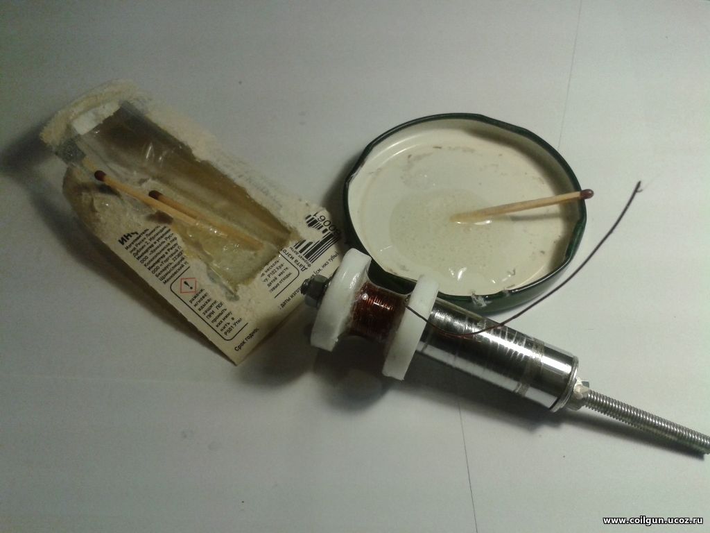
In general, it is not unavoidable to use epoxy for thin (4..6 layers) coils. 6) After the winding is finished, the wire is cut out with some excess left, and final coverage with epoxy is performed (if necessary) - it will make the coil more durable.
Fig. 9. Final soaking.
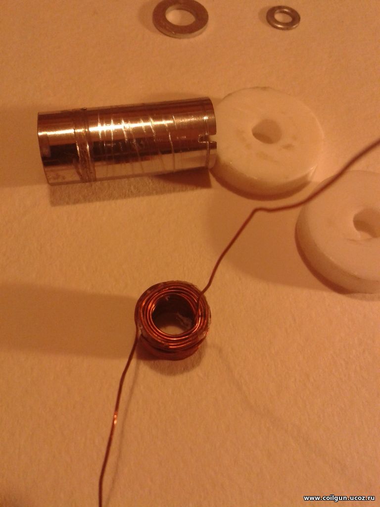
7) After the epoxy has solidified, we can remove the coil from the core. To do this, the nut (nut 3 in fig. 2) is unscrewed, the washers are removed, and nut 1 is carefully rotated clockwise - the metal tube pushes the teflon washer and shifts the coil to the end of the tube. The result is on fig. 10.
Fig. 10. The wound coil with dissasembled fixture.
The advantages of the proposed method are its simplicity and reproducibility (the only device can be used to wind many different coils). | |
| Views: 820 | |
| Total comments: 0 | |
