This investigation was performed as a continuation of the previous study to explore the efficiency of a halfbridge -based coilgun accelerator with high initial velocity of a projectile. For comparison, the performance of a simpler gauss-gun with damping varistor is calculated under the same conditions.
The problem was stated as follows.
Suggest we have two power switches with specified current and voltage ratings (I chose 400 V and 200 A which is close to avaliable details). In the coilgun, they may be combined as halfbridge (fig. 1(a)) or simply connected in series with addition of damping varistor parallel to a coil (fig. 1(b)). Peak current in the coil (200 A) and initial cap voltage (400 V) are in both cases the same, the difference is how the decrease of current is achieved - in the first scheme the cap is reconnected to the coil in inverse polarity (partial recuperation of the cap voltage occures here), in the second one a breakdown voltage of the varistor acts. As the transistors on the right circuit are connected in series, they withstand double rated voltage, so the varistor voltage may also be 400 V. I.e., the circuits containing components with identical parameters (and, hence, costs) are assumed.
 |
 |
| Fig. 1 (a). Principal scheme of the half-bridge coilgun. | Fig. 1 (b). Principal scheme of the varistor-damped coilgun. |
Another condition is the wasted energy per shot to be about 7,5 Joules. Ineer coil dia 8 mm, coil length 16 mm, cylindrical iron projectile is also 16 mm in length and 6 mm dia. Input velocity of the projectile 80 m/s (i.e. a stage of rather powerful accelerator is suggested). Fill factor of the winding is 0.85. For the halfbridge design, a special form of the coil is chosen which ensures maximum inductance for given wire resistance - it is outer dia is triple inner, i.e. 24 mm. In terms of this paper, such coil is "thick" and gives an optimal condition for recuperation. Under the above conditions these parameters correspond to wire caliber of 0.6 mm.
A range of the outer diameters (and wire calibers accordingly) of the coil was simulated for the varistor-based circuit, but the results below show only an interval close to maximum efficiency. Supplying capacitance is 5000 µF.
The aim was to reach maximum efficiency of the systems.
Under the described conditions, the solution is deduced to variation of the coordinate of activation (CA) i.e. the distance from the back end of the coil to nose of the projectile at which the switches are on. Two scrips were written - - bridge_one_cycle and coilgun_trans_ind_var, modelling halfbridge and varistor-based circuits, accordingly. Both scripts include Toff parameter which specifies a time form the begining of the process when the transistors are off. A correction considering energy loss on VD1, VD2 diodes in halfbridge is introduced by adding a constant 1.2 V to the voltage drop (which is about doubled drop on p-n-junction).
By the way, it appears that my suggestion that the voltage after shot can not be more than V0-1.2 (V0 - voltage before the shot) is wrong. Delta voltage may be only few tenth of the volt at high recuperation efficiency. Nevertheless, this doesn't affect other conclusions.
During the modelling process, there was a need to increse dimension of space around a coil (it is done by changing Vol parameter), as CA situated sometimes at more than 30 mm. Time step varied from 2 to 16 µsec to keep enough precision.
The results are depicted on fig. 2. It is clear that halfbridge performance is higher but not very much (despite the substantional recuperation). The optimal CA lies in distances more than twice the length of the coil, while the optimal CA for varistor-based circuit may be close to zero.
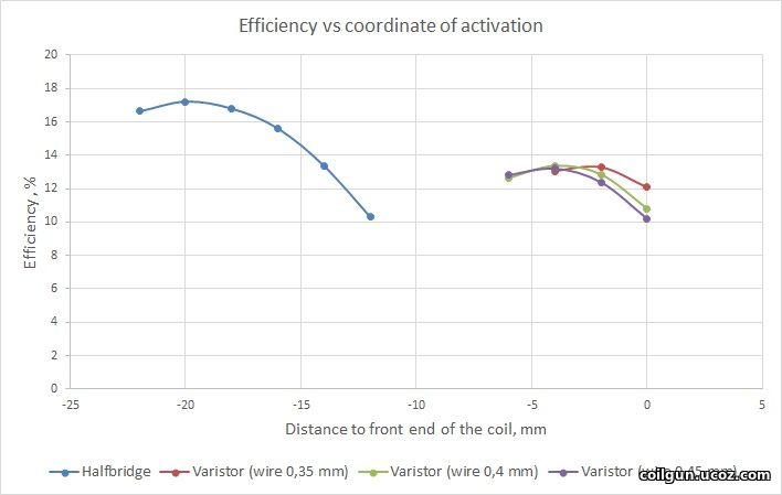
Fig. 2.
Fig. 3 shows the current waveforms for both cases (only 0.4 wire caliber is suggested for the varistor which corresponds to maximum efficiency). The pulse for the varistor is shorter which allows decrease of CA. The reason is simple: as the coil here is "thinner" than for halfbridge case, it allows steeper current slope.
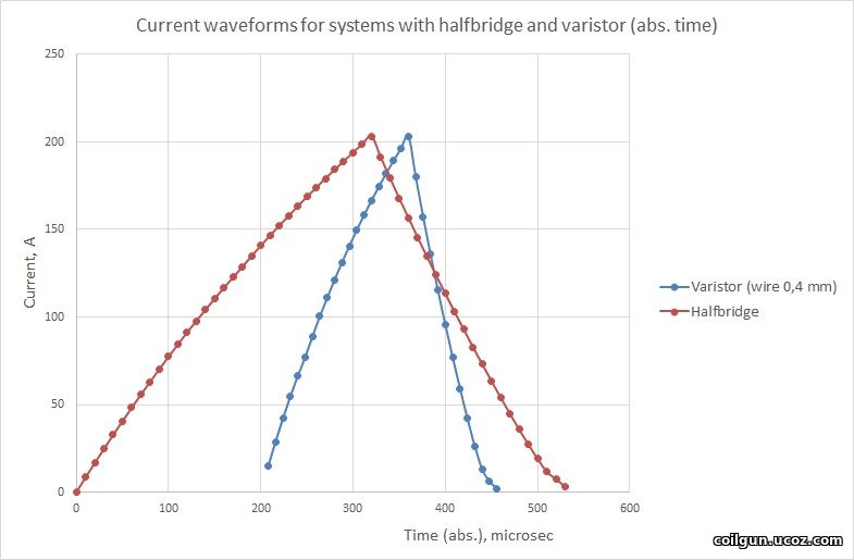
Fig. 3.
Two conclusions can be made:
1) As the varistor-based circuit gives faster current decrease and increase, it can be deactivated very close to "zero point" (ZP) - the place where acceleration force changes to deceleration one. As a result, a peak current occurs precisely at the site when the acceleration is maximal (see also here), which is an optimal condition to get high efficiency. At the same time, the switches must be driven in advance for the halfbridge. This fact explains why the performance of the halfbridge doesn't change drastically from one of the varistor (in spite of the huge profit from recuperation!).
2) A small region close to end of the pulses is distinguished on the graphs where the slope becomes flatter. Such a behavior may be caused by the iron core (projectile) going out the saturation at small (few amperes) currents in the coil.
Then, I decided to vary the diameter of the coil for the halfbridge to see how it affects on efficiency. Here, the wasted energy is no constant any more and ranges from ≈1 to ≈20 J. The grahps below are for the fixed diameter of the wire, and CA is a variable.
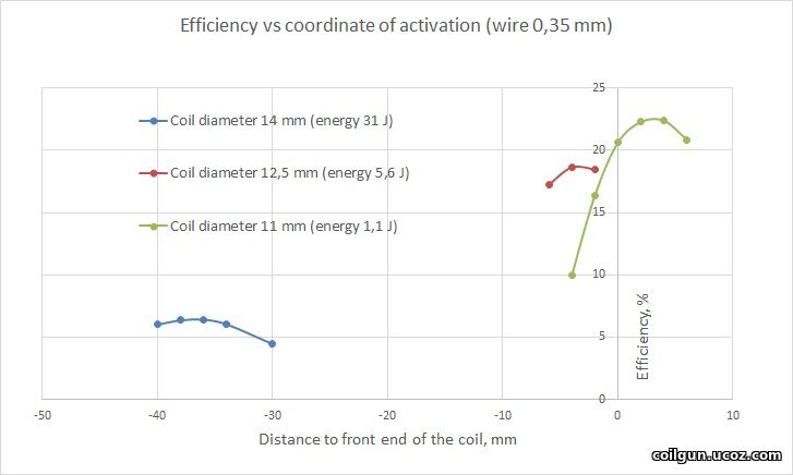
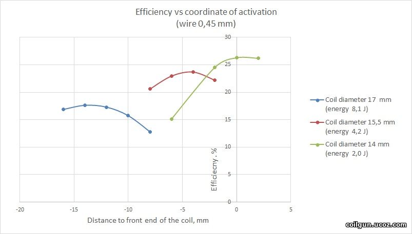
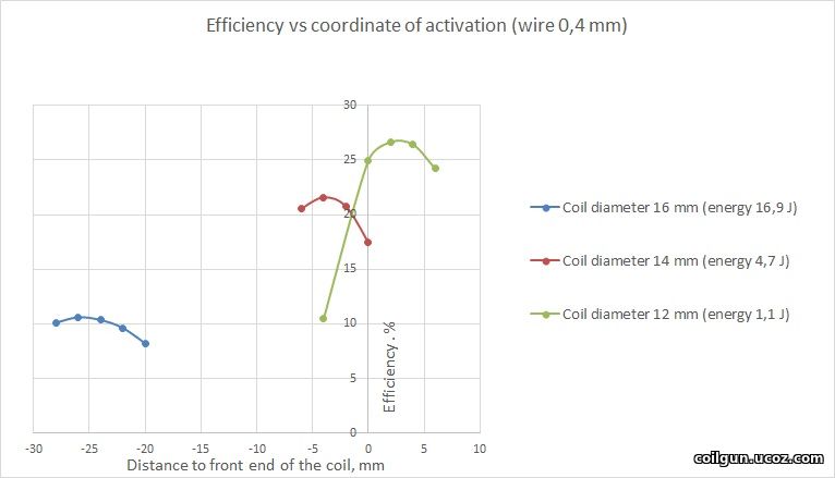
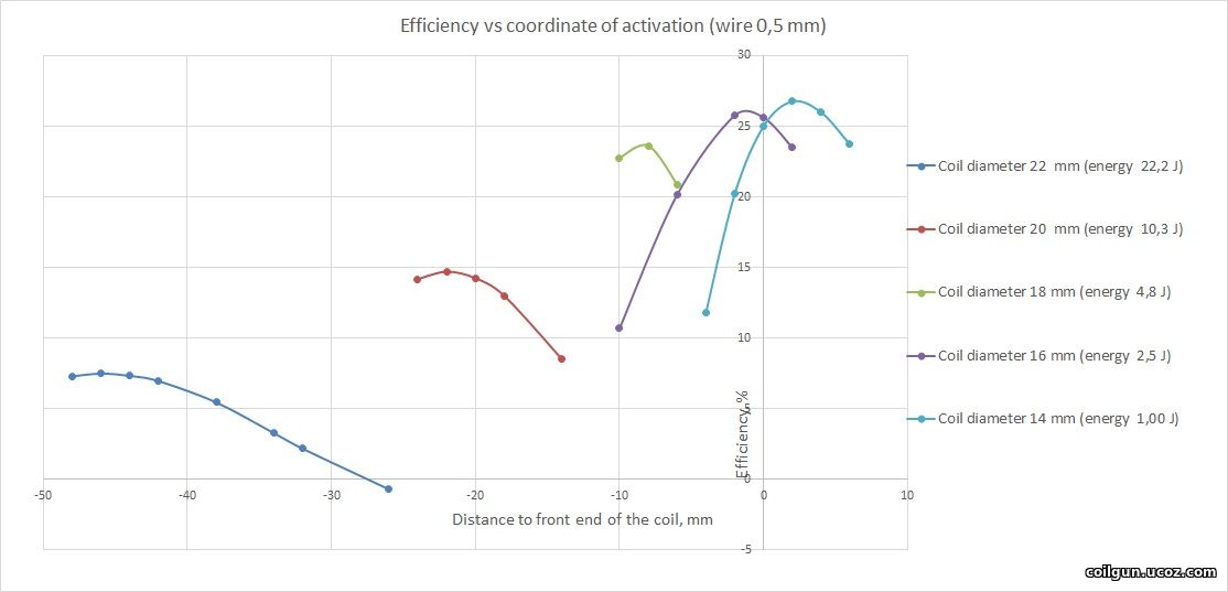
Fig. 4.
At last, after choosing an optimal CA for each wire caliber, we may try to examine the dependenies of efficiency vs exit speed (fig. 5, the wasted energy is of course different for each case). The values for varistor-based system are also shown (the corresponding dependencies vs coordinate were given on fig. 2).
Fig. 5.
Thus, we are able to coclude that, under a similar velocity gain and wsated energy, the halfbridge circuit with recuperation reaches about 2 times higher efficiency than "traditional" (for example, varistor-based) schemes do.