Coilgun EM-3 (“Electric bow”)
This coilgun was first constructed as table stand for investigation of multi-stage electromagnetic acceleration. Having finished all experiments, I decided to mount all parts of the stand into portable construction with charging unit (CU). So I had the coilgun to be presented.
Fig. 1. Coilgun EM-3 (more photos here).
The feature of EM-3 is using of arrow-shaped projectile with ferromagnetic head (that’s why it was called ‘Electromagnetic bow”). A number of experiments was conducted to determine an optimal form and method of manufacture of such projectile (which is told here). Nevertheless, the efforts were not in vain – the stable-in-flight projectile combined with high initial velocity of the multistage acceleration provides the characteristics of the coilgun, comparable with some models of bows and cross-bows.
Fig. 2. Arrows for EM-3. Total mass of each arrow is 5.15 grams, 2.85 grams of them is head.
In other respects I didn’t use anything new in comparison to known constructions. It concerns both principal scheme (commutation with SCRs with separate capacitor bank for each acceleration stage) and utilization of optical sensors for detecting the projectile’s position.
 Fig. 3. Principle of EM-3 operation.
This animation shows operating principle of EM-3: while moving through barrel, the non-transparent shaft of the projectile sequentially ceases shadowing the photosensors, which activate power switches of according stages. The first stage, in contrast, is activated only if the sensor is shadowed (this allows the shot only provided the coilgun is loaded). The picture below shows all basic parts of the coilgun, one should click to them to read detailed description.
Fig. 4. EM-3 layout.
Transparent tube in which the stabilizer is moving, is taken from foam spray; the one in which the head is contained – from 6-mm simple cocktail tube. Both tubes’ diameters are chosen to be inserted one into another with some tension – this allowed them to be attached only by friction. In general, I was to try a lot of different tubes while constructing EM-3.
Fig. 5. Diirerent tubes used in experiments. The long polypropylene one in the middle was utilized as projectile stabilier.
Accelerating coils were wound directly on “cocktail” barrel which was previously put on aluminum rod, small PCB squares were the separators. Then this construction was inserted into standard rectangle aluminum tube with a row of 10-mm holes drilled in one wall. Through those holes the wires soldered to the coils’ terminals were brought outside, and all internal volume was filled with fast-freezing epoxy. Previously small permanent magnet was put near the first coil to hold ferromagnetic head before a shot. Then the rod was extracted and resulting “barrel case” was mounted to strong angles screwed to 40-cm still stripe.
 |
 |
Fig. 6. Construction of barrel of ЕМ-3. Thin plastic tube is hold inside the box by pressure of the frozen epoxy.
Then the transparent tube was put on backside of the “cocktail” one, and two 4-mm threaded studs were passed through regular holes in the angles along the tubes, and fixed with nuts – they would be used as guides for PCBs of the optical sensors.
As a result, I had strong construction with standard elements and minimal work. Due to regular holes in the steel strip, it was easy to mount it onto wooden board used as base during the “table” stage of experiments, and then – on the portable coilgun’s forearm. Its only disadvantage is significant mass.
Whole “accelerating” part of EM-3 is depicted below. PCBs of the optical sensors can be moved along the studs and re-fixed by nuts – such simple method is used to fit an optimal moment to activate SCR of each stage. Besides, I drilled and threaded else one hole near backside of the transparent tube, and inserted there a short 6-mm screw – its purpose is to adjust an initial position of projectile which has critical influence on efficiency of acceleration.
 |
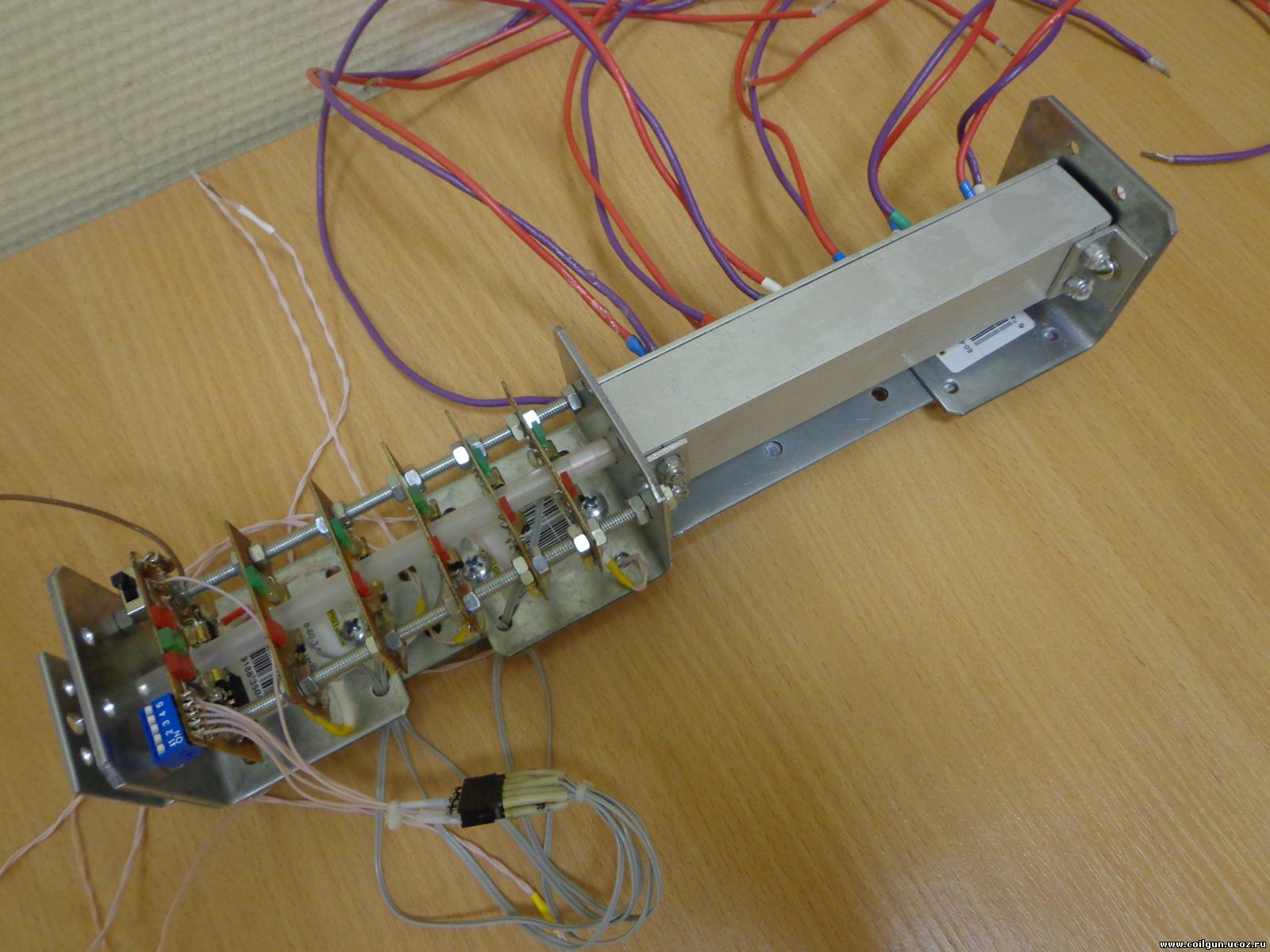 |
Fig. 7. Assembled acceleration part of EM-3.
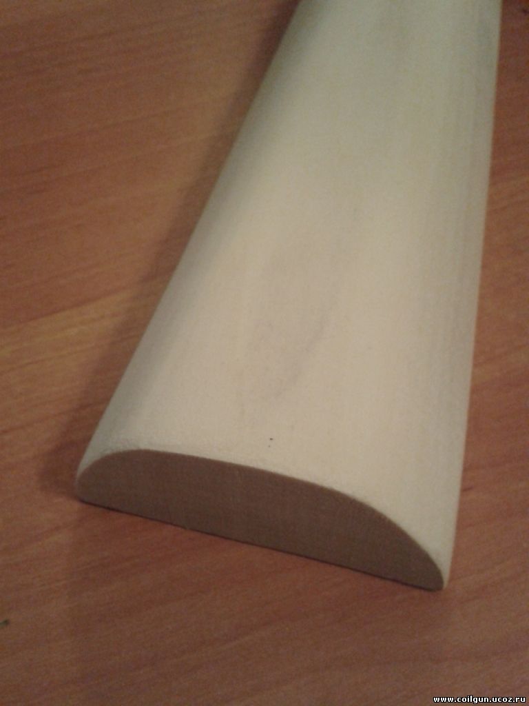
SCRs are BTA-41-600. This is one of the most powerful SCRs in plastic case available, it has even some redundancy in current in comparison to the maximal values which occur during a shot. Capacitors are K50-17 300 V, 800 mkF (4 pieces) and 400 mkF (10 pieces) (although they appeared to have less capacity, see below). The butt is standard (beech) for MR-512 pneumatic rifle. The forearm has demanded some work – it was cut from aspen board, grinded and covered by mordant and flax oil.
 |
 |
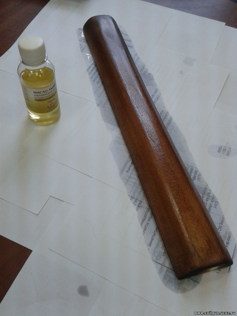 |
Fig. 8. Making the forearm.
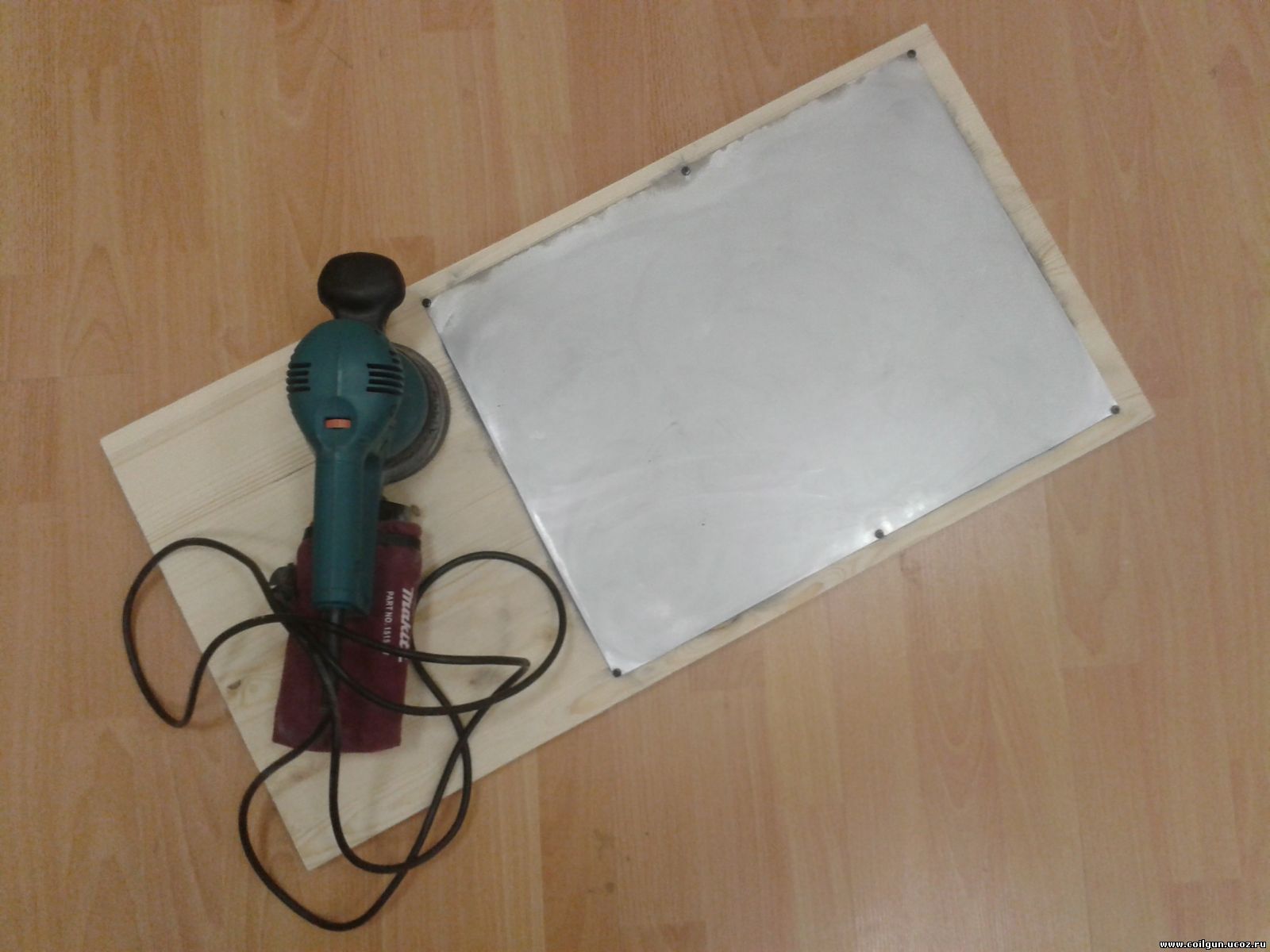
The case is manufactured from 1.5 mm aluminum sheet – grinded and bent as a cap of required dimensions. Automotive rubber seal is glued on the perimeter and impregnated with black “liquid rubber”.
 |
 |
 |
Fig. 9. Making the case.
End faces are two-layer plywood covered by black enamel and drilled to have holes for LEDs of indication, “on/off” switch and power supply cable (in back end), and for barrel and proximity sensor (in front end).
 |
 |
 |
Fig. 10. Ending elements.
Next photo shows the case in assembly. As one can see, it is strengthened with another one steel strip which divides the inside volume into 2 levels – the first contains barrel case and accumulator, the second carries the caps and control unit.
Fig. 11. Case in assembly.
Assembly was finished with standard collimator crossbow sight. It was mounted on Weaver rail attached to aluminum case with M3 countersunk screws.
That’s all about the structure of EM-3. Table below shows characteristics of the coilgun and each stage separately. All electric values are measureв with RLC-meter, speed – with IBH-716 chronograph. The maximum current reached in the stages is calculated according to formulae of this article. As it is seen, capacitance sequentially decreases which allows current to stay within reasonable range, and the same SCRs to be used in all stages. Besides, the measures capacitance (that was used for FEMM calculations) appeared to be substantially smaller than the nominal one.
‘Efficiency” column is finished by the integral value (final energy of projectile, divided by sum of energy of all capacitors, accounting that maximum charging voltage was ≈ 306V).
Preliminary calculations on EM-3 were made with my modification of FEMM script (given in this page of Arsenal forum). It was found out that all stages had to be wound with the same wire 0.6 mm dia. Length of each coil 20 mm, inside diameter 6 mm, outside one varies from 20.5 mm for the first coil to 13 mm for the last one.
Al last, the graph comparing calculated and measured parameters of the coilgun is below. The overlap is good, especially for 3-6 stages.
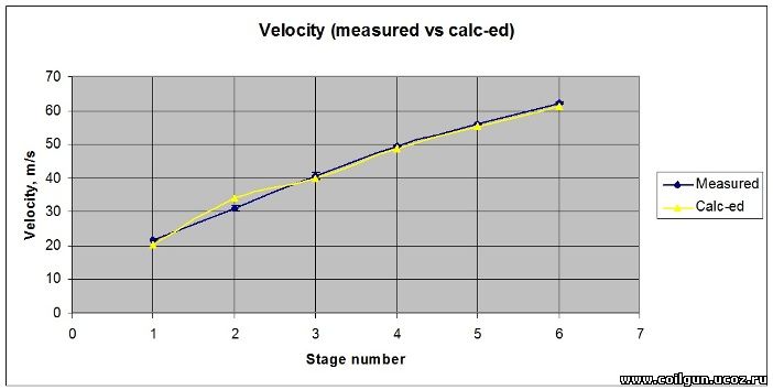
Fig. 12. Comparison of the real (Measured) and FEMM-calculated (Calc-ed) parameters of the multistage accelerator.
Here are some videos of shooting, including slow motion. About 2 hundred shots were made by this moment.
Much more photos are here and videos - here.
Sincerely yours, Eugen.