Creation of new gauss-gun with innovative design (which I called “bistage”) will be described here step-by-step.
This topology was investigated while constructing an inornate EM-2 coilgun, when I faced with a problem of low acceleration efficiency –driving the coils with simple SCRs could not give enough speed to a projectile. Quantity of the stages was limited by 2 not to overcomplicate the system. On the other hand, one was not able to use transistors on both stages, because the calculated current of the second coil went out the limits for MOSFETs (both for common-capacitor and separated capacitor topology of the stages). Paralleling the MOSFETs led to unacceptable price of the construction (the MOSFET was its most expensive part ).
At last, I joined the supply of both coils, but inserted a cheap SCR into the second stage instead of MOSFET. One MOSFET appeared to be enough to switch the first coil. Part of EM-2 scheme illustrating this, is below.
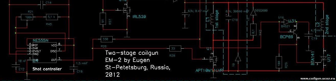
Fig. 1. Fragment of EM-2 coilgun circuit, visualizing the bistage scheme functionality.
As one can see, the timer drives the 1 stage’s MOSFET (as it is single, the driving capability of the timer is quite enough). Simultaneously, small cap C19 is being charged, which switches U17 SCR on at the rear end of the pulse through bcp69 transistor. As there is no more accelerating stages, the SCR fully discharges supplying capacitor giving an additional velocity to a projectile. It is clear, that this algorithm is simplest for the given construction, as we can, for example, open SCR with some delay after MOSFET switch-off (or beforehand) to get maximum efficiency, but I didn’t incorporate those options into EM-2.
To use this topology in a multistage accelerator one should mount few such blocks of one cap and two coils (hence “bistage” system) end to end and make a transistor switch (driving the first coils in all stages) common for the whole construction. One must also insert SCRs to all circuits driven by this switch to avoid simultaneous conduction in all windings, and the best choice to damp an inductive spike is one power varistor connected to the collector of the switch.
Fig. 2. Multi-coil bistage coilgun accelerator circuit.
What are the benefits of this circuit?
First, as we use forced switch-off in half of the stages, total efficiency is higher than in SCR topologies (although it is less than one in constructions with fully-controlled coils). On the other hand, the energy is utilized more completely here than in fully-transistor circuits as all capacitors are discharged after a shot.
Second (and the main) we can leave single controlled switch in the circuit. Why? Imagine that the projectile have passed the first coil in Nth bistage. The transistor is closed after that, and N2 SCR opens connecting the second coil to CN capacitor. While the switch is closed, the projectile passes that coil and the cap is being filly discharged. When the projectile flies to the next (N+1 th) bistage, the transistor switch opens simultaneously with (N+1)1 SCR which commutates the first stage of N+1th bistage, and the cycle repeats. Thus it is unimportant whether N1 SCR is closed or not, as CN cap is already empty. So, the velocity of the projectile does not play any role here, and bistages can be mounted end-to-end, ensuring high compactness of the coilgun.
Third, the capacitors of all bistages begin their discharge from equal (high) voltage, which allows to reduce the current through the transistor switch while maintaining enough power. This is the serious advantage over common-capacitor circuits. At the same time, ESR-looses are low as the energy of each cap is shared over two coils, which makes such configuration perspective for coilguns with high (100 m/s and more) projectile velocity.
1. Structural scheme.
Structural scheme of EM-4 gauss-gun is shown on fig. 3. It consists of the following basic units:
- Low voltage (LV) converter - it provides stable +15V for other parts of the circuit;
- High voltage (HV) converter which charges capacitors before a shot;
- Pulse generator;
- Power switching module;
- Projectile position sensors.
Fig. 3. Structural scheme of EM-4 coilgun.
LV and HV converters are mounted on single PCB ("charging-control unit"), and other modules - on other PCBs. This is to separate the low voltage part with high DC currents, and the high voltage pulse part dirctly participating in a shot.
2. Charging-control unit.
Principal scheme of the charging-control unit is shown in fig. 4.
Fig. 4. Principal scheme of the charging-control unit: LV (up) and HV (down) converters.
As one can see, the LV converter is constructed on LM78S040 IC connected in “buck-boost” circuit. It means that input voltage may be either lower or higher than the output one, which allows different accumulators being used in a range of approx. 5 V to 20 V (maximum voltage of 1N5817 diode). The same IC contains the battery control unit – when Uin decreases lower than threshold set by R6-R7-R9-R10 divider, the indicative LED HL4 lights on, and the other parts of the scheme are blocked by the signal from HL3-T1 optocoupler.
HV converter is built with control of the primary current using standard UC3843 PWM IC. However, the current sense signal is fed not to according pin of the IC, but to assisitive comparator DA2. This is because UC3843 has too high sensing threshold – 1 V – which would have led to excessive power looses on current sense resistor R14 in standard connection, because peak currents are rather high (20 A and more). Other elements of the comparator form the units of output voltage control, indication and shot permission according to scheme elaborated during creation of EM-3 “Electric bow”. The standard POL-15073 transformer is used, and power MOSFET and output diode are mounted on appropriate heat sinks.
Fig. 5 shows the PCB without components, fig. 6 – soldered PCB. All leaded components are mounted on top layer of the PCB, all SMDs – on the bottom. As one can see, nearly half of the board is dedicated to output section, which “shares” high voltage from intermediate cap C7 to 6 capacitor banks supplying the accelerating stages of the coilgun. It functions with the help of 6 diodes of different power rate and 6 isolated jacks which allow separated and safe connection and disconnection of the capacitor banks. The additional jack is mounted for ribbon cable which transmits the signals of permission and indication to other parts of the circuit.

Fig. 5. PCB without the components.

Fig. 6. Assembled charging-control unit.
Below is video of the assembled unit charging 1500 mkF to 400 V in about 4-5 sec from 7,4 Li-Poli accumulator.
3. Calculations.
It is important to execute some modelling of the coilgun to assess such parameters as pulse durations in each stage, amplitude of currents (for appropriate choice of the switches) and diameter of wires. It is especially serious in our case because the photosensors are planned to be fixed in EM-4 (in contrast to EM-3 where they are movable). So, it critical to understand whether we need additional processing of the signal form the sensors, or not.
The calculation was conducted for 3 initial speeds of the projectile: 3 m/s (meaning some velocity after "feeding" coil), 30 m/s (second stage), 60 m/s (last stage). The capacitances were suggested to decrease with stage number (totally 5 stages were planned): 450 mkF for the first stage (ESR 33 mOhms), 300 mkF for 2-3 stages (ESR 50 mOhms) and 150 mkF for 4-5 stages (ESR 33 mOhms). Initial voltage was 400 V, projectile caliber 5.5 mm, its mass 3 g, inside coil diameter (i.e. the outside diameter of the barrel) 7 mm. The case when approx. equal quantitis of the energy are dissipated on both coils of the bistages is suggested (i.e. the discharge on the first coil is down to ~285 V) - this is most appropriate according to preliminary evaluations.
As usual, FEMM was used, so the special script was created describing acceleration of the arrow-shaped projectile in two-coil system. The script is placed into appropriate page of the FEMM calculations section. The main conclusions are below.
1) All bistages can be wound with the same wire - 0.3 mm for the first coil and 0.5 mm for the second. The optimal length of all coils appeared to be 16 mm.
2) The optimal activation coordinate of all bistages is calculated to be - 2 mm. Delay before activation of the second coil(s) has very low influence and in fact may be set to zero.
The latter facts allow serious simplifications of the construction of our gauss gun - all bistages can be driven from the fixed photosensors directly, without any additional timing.
3) The calculated peak current in all coils doesn't make more than 100 A.
This allows using only one transitor switch to drive all construction (IRGPS60B120KDP IGBT is planned).
4) Calculated efficiency is rather high and makes more than 10 % for the last stage.
I assumed 6% effifency initially, which gives about 66 m/s with 108 J stored in caps (nine 150 mkF 400 V caps, the tenth is suggested to be utilized in "feeding" coil which pulls the projectile into the barrel) and 3 g projectile. But now I may hope to get more than 70 m/s...
Lets wait for the experimental results.
4. Power part.
Fig. 7 shows simplified scheme of accelerating module of EM-4. It consists of 5 accelerating bistages and one preliminary stage ("pre stage") which pulls the projectiles from magazine into the barrel. The first coil of each bistage is activated by according sensor which drives the SCR and simultaneously sends a signal into high-side or low-side line. The SCRs of 2nd coils are opened exactly when the first coils are deactivated by small additional windings which detect the induction spikes generated when the power transistor is being closed. IR-leds of sensors of all stages are connected in series and activated by external signal only during a shot - this decreases summary energy consumption.
Fig. 7. Accelerating part of EM-4.
The sensors are of two groups: low side (LS) and high side (HS). Their circuits are depicted on fig. 8. One can see that the only serious dirrefence is polarity of the output open-collector cascade - it is NPN for LS sensor, and PNP for HS one. Such decision allows many sensors to be connected to single line in parallel, and on-off cycling of the power transistor key which commutates first coils of the bistages through "Power switch drain" bus (more details below).
 |
 |
Fig. 8. Optical sensors - low side (left) and high side (right).
Besides, the sensor have power output to drive the gate of appropriate SCR, and strobe input. The projectile loading detector (it is "pre stage" sensor) is constructed according to HS scheme, but the stage is simpler - this is single coil driven from the sensor-controlled SCR.
The transistor and pulse generator will be placed on single PCB, which scheme is shown on fig. 9.
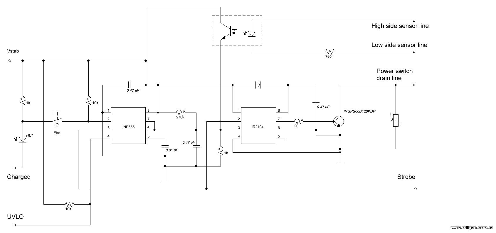
Fig. 9. Pulse generator.
The pulse generator is based on simple 555 timer and is activated when the capacitors are charged ("Charged" signal from charging-control unit is active, see section 2) and UVLO (battery discharge signal ) is inactive. The pulse from the timer goes to driver IC which controls the gate of IGBT switch, and to IR-led chain of the accelerating part. The same signal blocks the capacitor charger through "Blank signal" input. SD pin of the driver is fed from an optopair which in turn is connected between LS and HS lines. So, IGBT is open when both those lines are active (at least one optodetector of each line is on).
All this circuit must function as follows.
When "Fire" button is pushed (S1 on fig. 9) the strobe pulse is generated which activates IR leds and all opto-sensors. Provided the projectile is inside magazine, the pre stage sensor opens appropriate SCR and pulls HS line to Vstab. IGBT is yet closed as LS line is inactive. When the projectile reachs the detector of the first stage, T11 SCR is on and LS line is pulled to ground activating IGBT. So the first coil of the bistage is switched on and stays so until the projectile moves out from the magazine and pre stage detector is lighted by according IR-led. From this moment HS line goes to high-impedance state, and the transistor closes. Positions of the detectors (and length of the projectile) are chosen in such a way that this happens when the nose of the arrow is near the fromt end of the second coil of the bistage. Now the induction pulse activates T12 which feeds this coil, and the next tact of the process begins when C1 capacitor discharges totally. IGBT is off until the projectile reaches the sensor of the second bistage, and the next cycle is launched.
Hence, all five stages are driven by two signal and one power bus. When this method applied to coilguns with 10 and more stages, it would show even more advantage over traditional "one sensor - one line" scheme. The only sophisticated moment is the accurate choice of distance between the sensors and projectile length - they must correspond to optimal conditions defined in the pevious section.
The principle described above is illustrated on animation below.
Fig. 10. Principle of operation of multi-coil bistage electromagnetic accelerator.
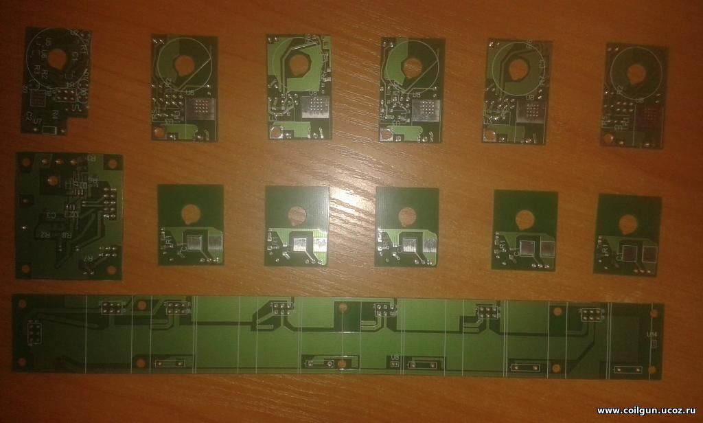
Fig. 11 shows PCBs or the accelerating part of the gauss gun before and after mounting the components.
 |
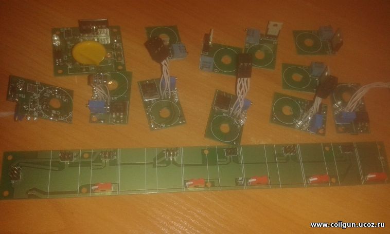 |
Fig. 11. PCBs for accelerating part of the coilgun.
Short video below demonstrates testing of sensors - they are mounted together with the help of brass bars, and small nail is thrown inside as a model of the projectile. The separate PCB underneath carries yellow LEDs (they are connected to the anodes of SCRs in parallel with power resistors and light up sequentially when the according stage is activated, except for one - it is not connected as pre stage is always on in this experiment). Blue LED is on when LS and HS lines are both activated, so the differential action of the construction is clear. The activation of the stages is shown by green LEDs.
5. Pojectiles and a feeding system.
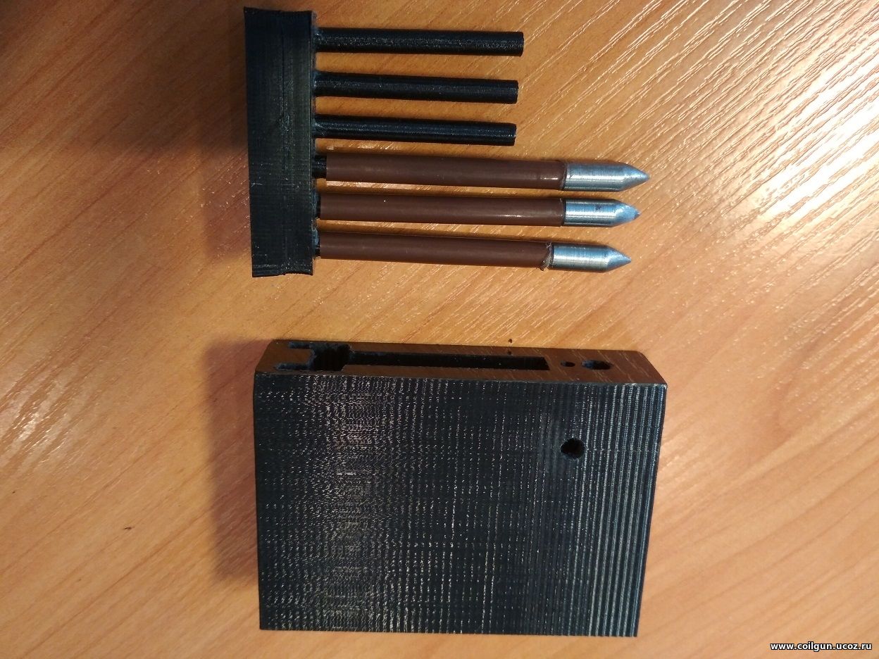
Special arrow-like projectiles were manufactured for EM-4 from machined 6 mm nail cuts and plastic cocktail tube (see fig. 12). Conclusions of this my work were used to determine the dimensions of the details. As seen, a rear part of the tip bears an annular cut of about 5 mm depth - this is made for tighter contact of the metal with the stabilizer which were connected by a simple thermo-glue. Mass of the tip makes about 2,7 g, stabilizer with glue - less than 0,3 g. The tip's diameter is 5,5 mm, length 16 mm, overall length of the projectile 57 mm. Thus, all the starting conditions taken for previous modelling (see sec. 3) are maintained. So, we may expect that the modelling results will be close to reality.
 |
 |
 |
Fig. 12. Making stabilized projectiles for EM-4. |
A feeder had initially been planned as the simplest one - gravitational type, where the carged must roll into the barrel by their own weight. But it appeared not an easy task, and needed some replicas to have been done. A final version of the feeder is shown on fig. 13.
 |
 |
 |
Fig. 13. The gravitational feeder for EM-4 coilgun. More detailed photos can be found in an album dedicated to this gaussgun. |
The feeder consists of two 3D-printed parts: container and slider, the latter has 6 cylindrical charge holders - they enter the hollow stabilizers and prevent a projectile's misalignment during a feeding process. An inner bottom surface of the container is semicylinder repeating a form of the barrel tube, which must have a longitudinal notch - the projectile stacks into the notch by its tip and is fixed by a small cylindrical magnet placed in a special blind hole in a lower face of the container (see fig. 13). Another smaller hole is made close to the former - it is through and serves for emergency pushing the slider out upwards. An attractive force of the magnet is enough to hold the fully carged slider in an "upside down" position, which means that the feeder will not fall out if the gauss gun is overturned ( although it will not recharge, of course).
The slider moves down sequentially at every shot, making a next projectile stand into its position in front of the accelerating coils and obscure the phototransistor of the pre stage from its IR LED (according cuts are made on the sides). The next shot will not occure if the slider is empty.
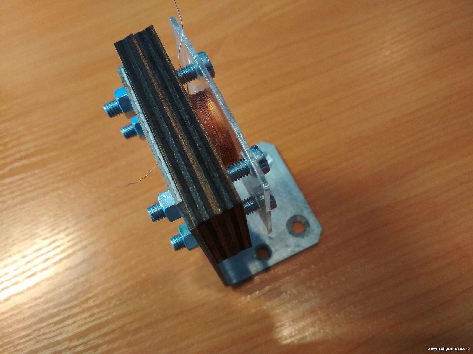
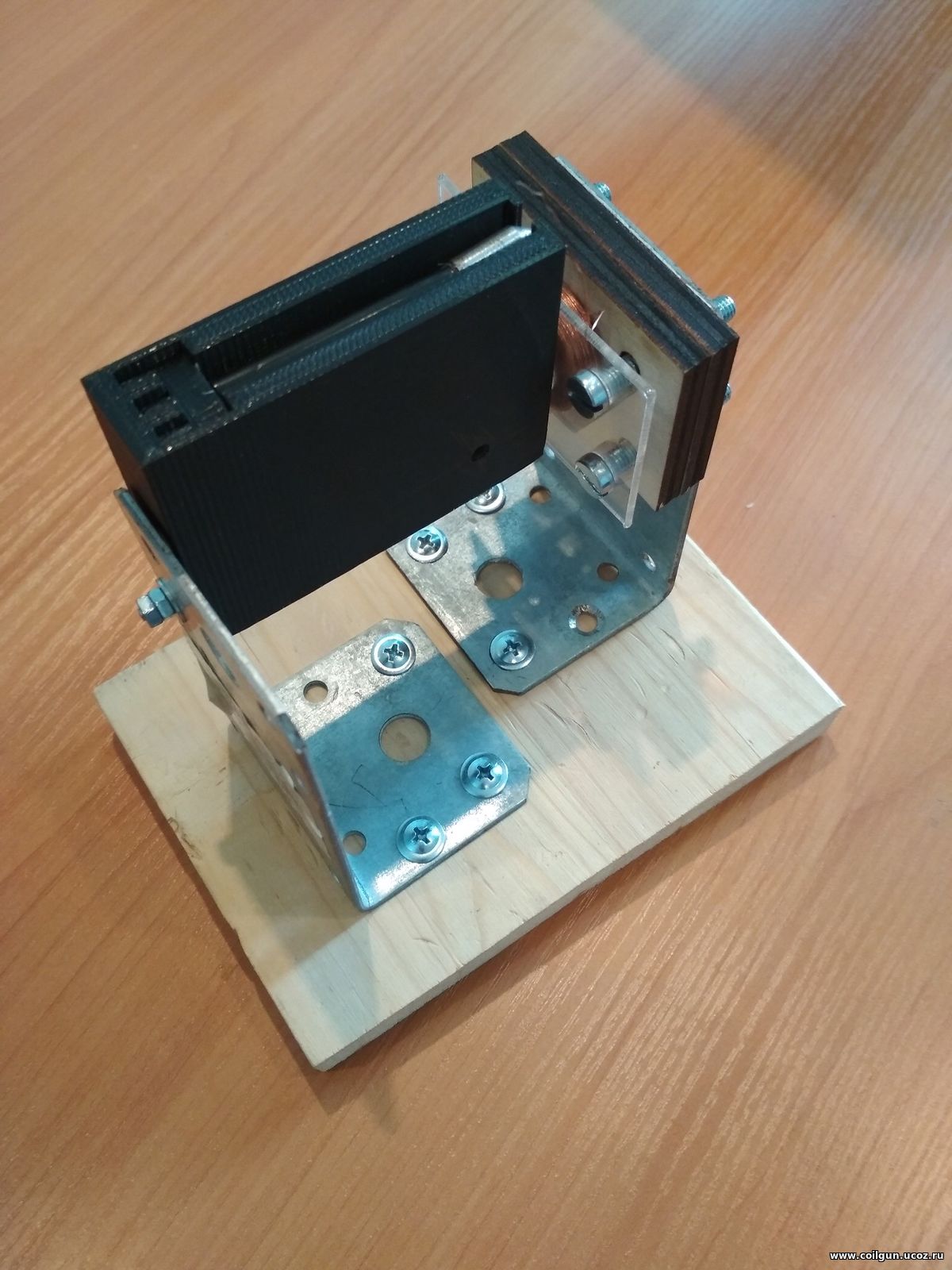
The feeder was tested with the help of a special stand collected with two steel corners and appropriate woodboard (fig. 14). Thin-wall 7 mm thermo-glued brass tube was used as a barrel. A special pancake coil of high outside diameter (to "catch" the projectile with far enough initial position) was wound to simulate pulling of the projectiles inside the accelerating part, its parameters are: out dia 23,5 mm, length 6 mm, 570 turns of 0,22 mm copper wire woun accoring to the technology previously described (all other coils of the coilgun will be wound similarly).
 |
 |
 |
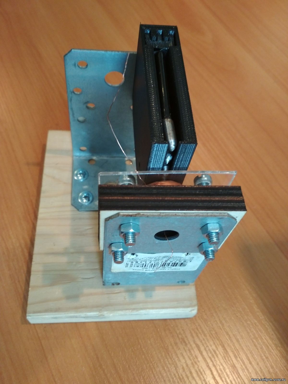 |
Fig. 14. Building a testing bench for the feeder.
A video of testing is below.
A single electrolytic capacitor 400 V x 150 mkF was utilized in pre stage. Its energy is not high, so the rate of the feeder could be enhanced up to some shots per second, but I limited it to a value close to one expected in a real assembly (when a whole capacitor bank is charged after each shot).