In addition to the main design of electromagnetic mass accelerators discussed on this site (namely, a ferromagnetic projectile is pulled in by a winding with current), there are many more configurations of them. In the first half of the XX century, the most widely studied type of inductive accelerator was a construction in which one coil was repelled or attracted by another one. For some reason, it became interesting for me to study this process in my activity, for which I went through the beaten path of modeling in FEMM - fortunately, this program has all the necessary capabilities for this.
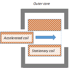
Petrovich's website has a ready-made script for calculating an induction accelerator, but it, in fact, simulates a traditional reluctance coilgun in which the iron core is replaced by a coil connected in series with a retractor winding, outside of which a magnetic core can be placed (see Fig. 1 on the left). Meanwhile, real structures are most often arranged differently - in them two ring windings close in diameter repel each other, moving on top of the central magnetic core (Fig. 1 on the right).
 |
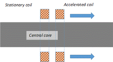 |
Fig. 1. The inductive accelerator modeled by Petrovich's script (left) and the one I needed (right).
So I decided to write my own script "from scratch".
Among other things, I wanted to introduce the consideration of all factors, including the calculation of the dependence of the inductance of coils on the flowing current in a nonlinear system (i.e., in the presence of a ferromagnetic core). I will explain in more detail what is being discussed.
Let's write down the Kirchhoff equation for one of the stages of an electromagnetic accelerator (no matter of what design):
U = i·R + L·(di/dt) + i·(dL/dt) (1)
The total inductance L of the system depends on the number and method of connecting the coils.
In our particular case (two series-connected repulsive windings with their own inductances L1 and L2, in which the same modulo multidirectional current i flows) L = L1 + L2 - 2 · M, where M is the mutual inductance of the coils.
In (1), the inductive EMF is explicitly written, depending both on the derivative of the current in time and on the derivative of the inductance. The EMF U standing on the left in this equation is equal to the voltage of the power source connected to the coils.
Since the inductance of the system L = L(i,x) depends both on the x coordinate and on the current in the coils (since we have a nonlinearly magnetizable medium with a magnetic conductor), the derivative of the inductance in time can be written as
dL/dt = (dL/dx)(dx/dt) + (dL/di)(di/dt) = v·(dL/dx) + (dL/di)(di/dt) (2)
Here v is the velocity of the projectile.
Thus, generally speaking, there are 3 components of inductive EMF (all of them have the dimension of Volts):
- born by vairation of current L·(di/dt)
- caused by mutual movement of the coils i·v·(dL/dx)
- due to inductance change of (even stationary) coil with current i·(dL/di)(di/dt).
The latter component in the accelerator of the type under consideration will be different from zero only if there is an additional ferromagnetic core, while in conventional gauss-guns the role of such a nonlinear element is performed by the projectile itself. Nevertheless, even for traditional coilgun calculations, the influence of this factor is usually neglected. Petrovich's script, which I mentioned above, was no exception.
In my script, depending on the presence /absence of a core (the criterion for this is its diameter Dmag - if it is more than 1 micron, then the system is already considered nonlinear), the calculation procedure is adjusted accordingly and the calculation of the inductance derivative on the current is introduced at each iteration step. Among other things, the output file contains a series of values of the inductance of the windings, their mutual inductance, as well as all three values of inductive EMF., described above (the last of them is always zero if Dmag < 1 µm).
By default, the accelerated coil (liner) and the stationary one (pusher) are assumed to be the same, and the length of the magnetic circuit is three diameters of the coils in the direction of acceleration, and two in the opposite direction. If desired and owned by FEMM, these preset parameters can be changed in the program body. In addition to the usual geometric parameters (the outer and inner diameter of the coils, the diameter of the magnetic core, the initial distance between the coils), you can also set the mass Ms of an additional body (projectile) accelerated together with the liner - such types of accelerators are often proposed to be used to launch cargo into outer space.
As a result of calculations, the script outputs the usual set of parameters (output speed, efficiency), as well as the mass of the coil and the magnetic circuit (if any).
As an illustration, I will give the results of calculating the dependence of the efficiency of an inductive accelerator powered by a single 450 V, 470 μF capacitor. The parameters of the coils were as follows: the diameter of the copper wire 0.5 mm, length 5 mm, inner diameter 20 mm, outer one 30 mm (with a standard winding density of 0.8, this corresponds to the mass of each coil makes 9.4 grams). The calculation was carried out for a system with an axial magnetic core with a diameter of 15 mm, as well as without it.
 |
 |
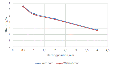 |
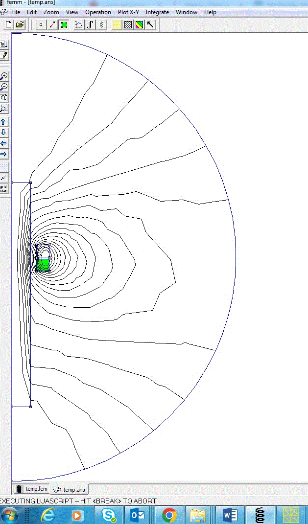
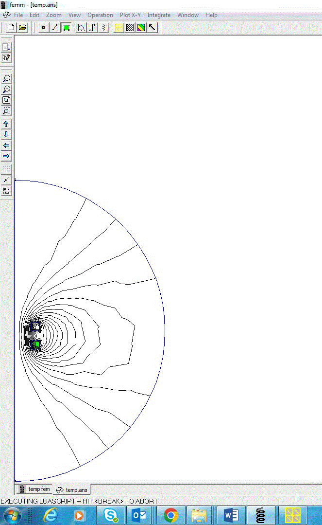
Fig. 2. The process and result of calculating the parameters of the induction accelerator by the proposed script.
The script itself can be found here: http://coilgun.ucoz.ru/Inductogun/inductiongun.lua
As can be seen, the presence or absence of a magnetic core, even with such small energies of the system, affects the efficiency very little. This is similar to the behavior of "traditional" gauss- guns with iron shells, but here the situation is even more pronounced, since the field strength in an induction accelerator is usually much greater than in a conventional coilgun.
A distinctive feature of induction launchers is an increase in their efficiency with an increase in the "pumped" energy. I have conducted several simulations confirming this pattern, but their detailed analysis is beyond the scope of this publication - perhaps I will return to this issue later.
Sincerely Yours,