Practice demonstates that voltage converter which charges the capacitors before shot is most complicated in fabrication and responsible part of a coilgun. All questions about these conveters are discussed for example on this forum, I won't stop to focus on them here, just emphasize the basic moments:
1) It is flyback converter (FC) which is most suitable for coilguns, because it functions with variable load (up to short circuit), i.e. the conditions which arise when large capacitance is being charged.
2) As EM-3 coilgun is build on uncloseable switches (SCRs), the charging must be stopped during and some time after the shot (otherwise the SCRs will not switch off). Thus the converter must be tied with the unit which controls the switches.
3) It is desirable to have system of control and indication ("Caps full", "Battery low" etc.).
4) FC must operate in sufficiently wide range of power supply voltage (in our specific case of Lead accu - from 10 to 13 volts).
Basing on these preconditions, I created the control-and-charge unit, which scheme is depicted on fig 1.
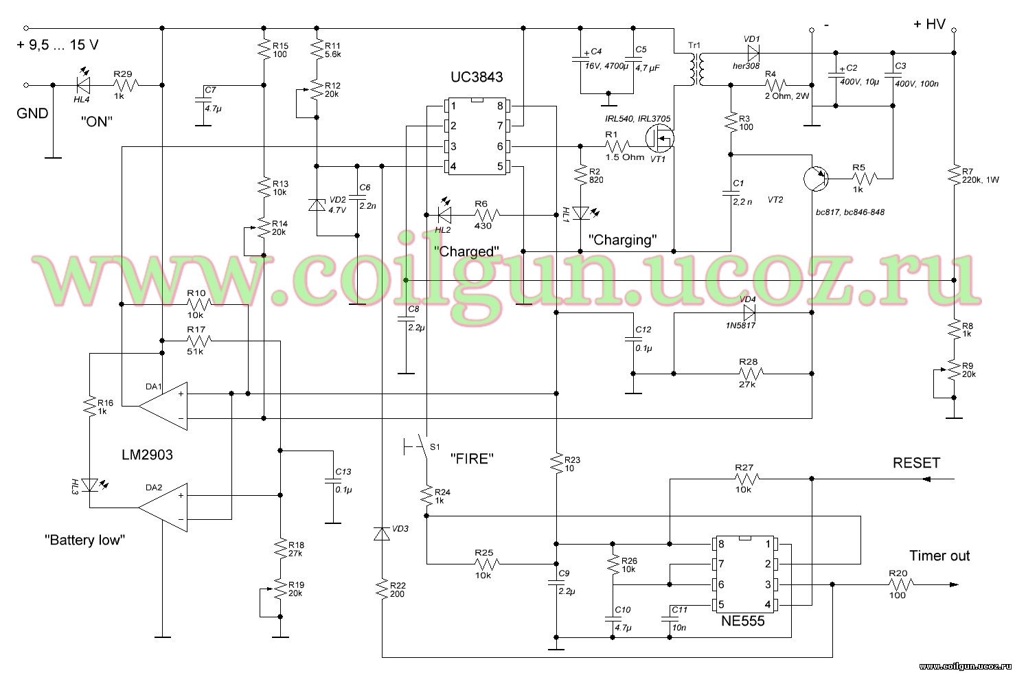
Fig. 1. Scheme of control unit of ЕМ-3.
In sipte of rather awesome view, the circuit is simple. Its core includes FC on IC UC3843 equipped with two feedback chains: output voltage chain (fed to pin 2 of the IC) and secondary transformer current (through VT2 transistor). The similar circuit was suggested here, but in my converter it is simplified by using comparator LM2903. Another feature of this FC is utilization of the standard transformer POL-15073 by Premier Magnetics (although, in nonstandard connection) - this allowed to avoid traditional in such cases and tedious procedure of calculation, winding and tuning the self-made transformer. Power output of FC is regulated by variation of the on-state of VT1 switch with the help of potentiometer R12.
Reference voltage output of UC3843 +5V is used to supply 555 timer, which generates 50 ms pulses when S1 button ("FIRE") is pressed - these signals activate the system of optical sensors, which directly drive the power swictches of the coilgun. Connection of S1 to pin 1 of UC3843 provides unintentional shot protection - timer can operate only when capacitors are charged. The timer can be blocked by RESET input by a signal from optosensor, which detects the projectile to be inside the barrel (to avoid blank shot; this sensor is situated on starting stage board of the coilgun), and from IR-proximity sensor.
Dual comparator LM2903 tracks power supply voltage and has two thresholds, which are set by R14 и R19 potentiometers. This allows early (before the battery discharges to dangerous level) activation of HL3 LED, connected to the first comparator. Under further discharge the second half of the IC activates and stops the circuit through Current Sense input of UC3843. The latter comparator is connected to the abovementioned feedback from transformer, which halts the converter, unless the secondary current falls to safe level - in such a manner the varied duty cycle of UC3843 is organized.
The ciruit is placed on double-sided PCB, all SMD-components on one side, all leaded - on another side. PCB dimensions accord to Pb accu 12Vх1,2 Amp*hours, which it is situated above inside the case of EM-3.
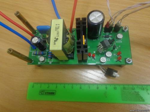
Fig. 2. Control unit of EM-3.
As it is seen, power transistor VT2 is mounted on heatsink, but it heats very moderately in real working conditions of EM-3, so I could have cancelled it. Capacitor battery of ≈ 7000 mcF is charged in 15 sec by this converter, and current in final stage of charging makes some more than 5 Amps. On the photo, besides the start button S1, an additional key is seen - it commutates 2nd and 8th pins of UC3843 and is used during tunuing of the circuit.
This control-and-charge unit is able to serve in any SCR-based coilgun. Any power source in voltage range shown in fig. 1 is appropriate, one should only set the warning and shut-down thresholds of the comparator by R14 и R19 potentiometers.