Simple electromagnetic device for feeding projectiles to accelerating part of a coilgun is presented. The principle of its operation is shown in fig. 1
Fig. 1. Principle of operation of the sequential feeding system.
One can see that this is nothing else but linear electromagnetic engine - the "travelling wave" of magnetic field formed by sequence of coils provides movement of a ferromagnetic core (projectile) to intended direction.
The animations shows the single projectile being moved, but after some reflecation it becomes obvoius that the system is able to function with any amount of projectiles situated in any position inside. The feature of this feeding system is absence of moving mechanical parts and soundless. In fact this is low-power coilgun supplied not from traditional capacitors, but from low-voltage source (for instance, accumulators) directly.
The purpose of the experiment was to determine values of current, pulse durations and electric power necessary to the system operation in various space orientation.
It should had been right to use a microcontroller to form controlling signals, but I did in simpler way by using level controller IC LM3914. Provided linear ramp on its input, this IC generates the required signal sequence. Final circuit of the controlling part is depicted on fig. 2, power PCBs - on fig. 3.
Fig. 2. The control circuit of the feeding system.
Рис. 3. The power circuit of the feeding system.
Pulse duration is set by R5 potentiometer on fig. 2, current in feeding coils - by U2 voltage.
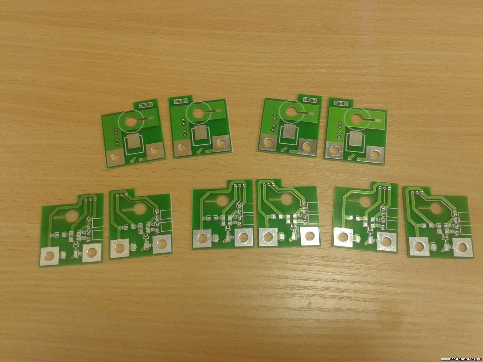
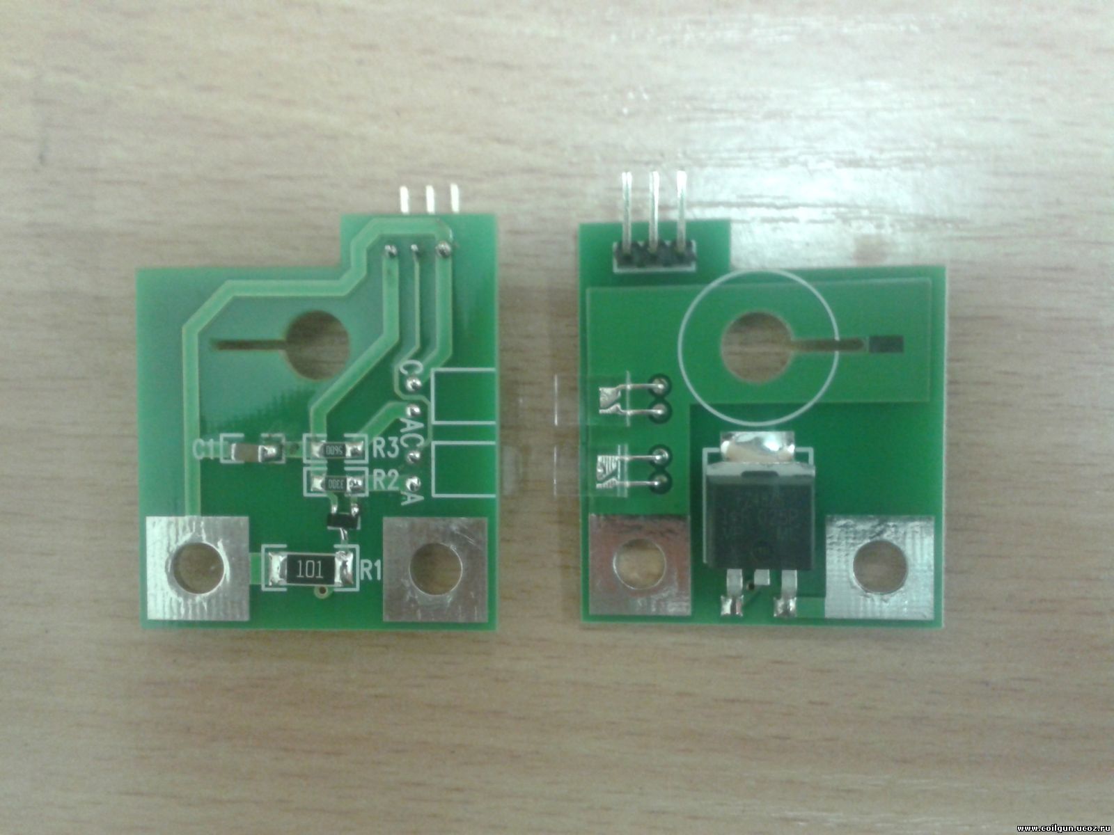
The coils are commutated by power switches IRFZ44 which are mounted on little similar PCBs together with driver circuits on VT1. The PCBs are different on S1 connector position only - it is situated on the right for one half of PCBs, and on the left for another. The PCBs are mounted chequerwise to make the connectors accessible. LEDs HL1, HL2 serve for indication (green lights when the power is supplied, red lights when the specific stage is "activated").
Fig. 4 illustrates mounting of the PCBs.
 |
 |
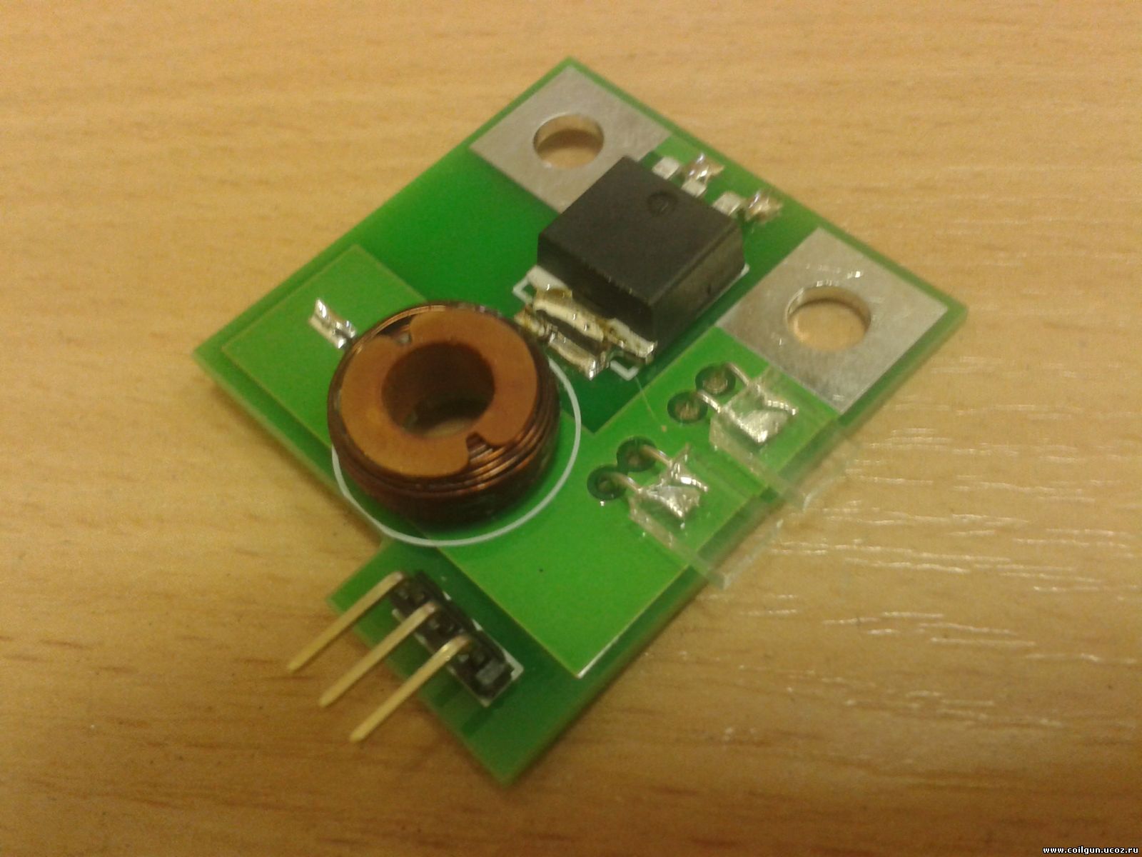 |
| Fig. 4. PCBs of the feeding coils. |
Feeding coils are wound with 0.2 mm wire on standard B14 frames with inner diameter about 6 mm. The coils' parameters are shown in table 1. Each coil is glued to according PCB, and PCBs are mounted on two pieces of threaded rod, which are conductors for "+" of the power supply (U2) and "ground".
| Parameter |
Value |
| Length, mm |
5 |
| Inside diameter, mm |
6,5 |
| Outer diameter,mm |
13 |
| Number of turns |
74..77 |
| Inductance, mcHn |
42,3.....42,9 |
| Resistance, Ohms |
0,422.....0,423 |
Table 1. Parameters of the feeding coils.
In summary 9 such stages were wound, which (together with gaps between the coils and PCBs' thickness) gives total feeding length about 75 mm. As the system was used for 4.5 mm balls, the capacity appeared to be 17 balls.
One should note that the gap increase leads to expansion of the feeding length, but decreases the puliing efficiency (i.e. more power is needed), as magnetic field reduces rapidly between the coils.
The final system is shown in fig. 5 (more photos are here, videos - here). At first I glued a permanent magntec to the last PCB to investigate how the ball is pulled (here is video but but in poor quality - shot from a phone). System parameters are listed in table 2.
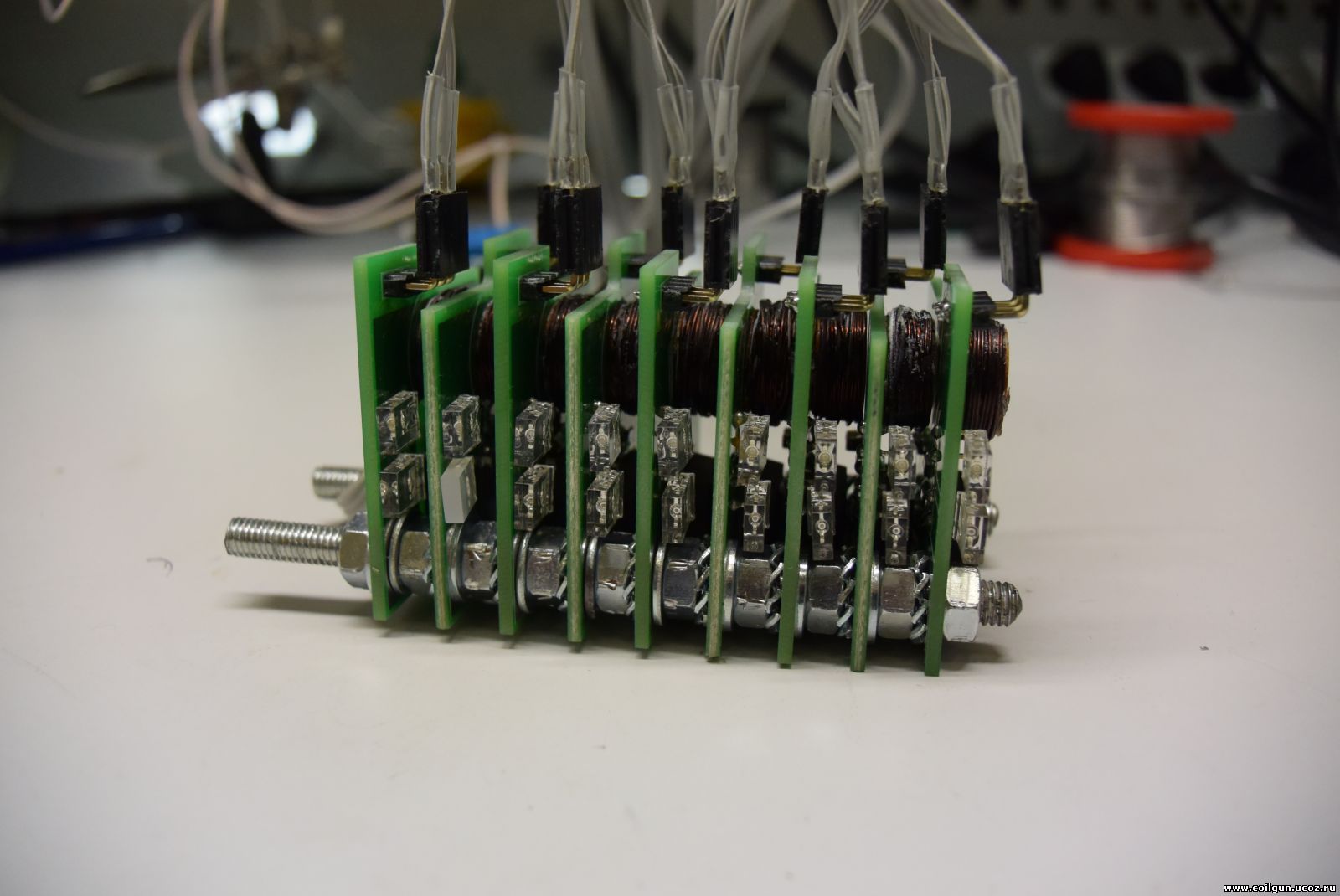
Fig. 5. Mounted feeding system.
|
Threshold voltage
U2 thr, V
|
Duration of feeding
through whole system
Т, s
|
| 4.25 |
2.40 |
| 5.3 |
1.50 |
| >6 |
0.82 |
Table 2. Dependence of threshold operation voltage on pulse duration (vertically oriented system).
Then I decided to model the operation in assembly with a coilgun, where a ball is pulled out from the feeding system by first acceleration stage. To do this I constructed small additional circuit (fig. 6) and mounted it instead of the peramnent magnet. This circuit needs high voltage power supply (HV), which can be taken from the coilgun's capacitor charger.
Fig. 6. "Pulling"circuit. According to signal from 10th pin of LM3914 the charging channel for С1 through optoswitch is closed, and Т2 opens Т1, which forms current pulse in pulling coil.
Operation of the system in such mode is shown on video below.
So, the experiment was finished.
One can see that PCBs are not very densely occupied with components - they can be easily diminished enough to be inserted into a standard gun handle (especially if SMD-components are used - it is possible as operation currents appeared to be relatively low).
|