| Home » Articles » Theoretical papers » Coilgun calculations |
In an article called "Investigation of the recovery efficiency in a halfbridge electromagnetic accelerator" I calculated efficiency of recuperation of a half-bridge launcher in dependence on different parameters such as initial velocity of projectile. FEMM modelling of the total (including recuperation) efficiency of acceleartion was also announced. Current paper gives the results of the calculation both for half-brodge -based circuit and comparative scheme with damping varistor connected in parralel to the coil. The two circuits are shown on fig. 1.
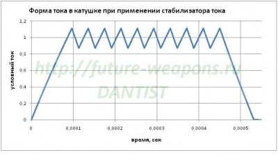
The initail conditions were: projectile velocity 80 m\s, capacitance 5000 mkF, voltage 400 V. I.e. a substantionally powerful launcher is under analysis, which starting voltage could be 450 V (it accords to the energy 4502*5000/2 000 000 ≈ 506 Joules saved for instance in 5 450Vx1000 mkF caps and is likely to be close to a limit for a portable construction), and decreases to 400 V till the suggested moment. Assuming a half of the stored energy is wasted per shot, a final voltage may be about 318 V. In other words, a stage situated somewhere in a middle of a barrel of multistage system (with something like 120 m/s exit speed) is modelled. The geometry of the system was as follows: the length of coil and projectile 16 mm, inside coil diameter 8 mm, cylindrical projectile caliber 6 mm. The simulation was performed in a range of outside coil dimeters (and accoording wire diameters) up to 24 mm (i.e. "thick" coils following a gradation made here). In the latter paper it is demonstrated that the recuperation efficiency for such diameters of the coil and velocities of the projectile goes to saturation and makes about 80 %. So, it would be reasonable to expect very high total performance of acceleration in the system. Maximum current of 200 A was an additional limit for the switches. So, both circuits on fig. 1 utilize equal semiconductors with 450 V voltage and 200 A ratings, which is around what we really have for power Si-based IGBTs today. Power diodes VD1, VD2 in the half-bridge circuit must withstand 450 V reverse voltage, and so must VDR varistor in 1(b) scheme. Consequently, the cost of power semiconductors for both circuits is approximately equal. Another schemotechnical things are more complicated. While two switches connected in series may (and must) be substituted by one twice-voltage-rated transistor in the varistor-based circuit, there is no such an opportunity in the half-bridge, and, besides, they need separate driver schemes with "bootstrapped" voltage, as it is done here. Similar reverse voltage - 400 V is applied to the coil in both cases ensuring approximately equal current slopes (suggesting the same coils of course). All other details of the calculation (including the scripts) are given on this page. Before we go down to analizing the results, let us make some important notice. All the examination made in "Investigation of the recovery efficiency in a halfbridge electromagnetic accelerator" suggests that the current pulse in a coil is triangular - the switches are activated, the current rises up to its maximum value, then both switches are closed synchroniously and current begins flowing back into a cap, "pumping" it up with a residual magnetic energy. But there is a gap between those two states in real coilguns (like one linked above), when only one switch is on and current is freewheeling in a coil decreasing slowly on its ohmic resistance, or the second switch is being activated for short periods of time supporting the current about some preset value (i.e. current stabilization takes place).
Fig. 2. Theoretical forms of current and voltage when the recuperation cycle goes immediately after the "storage" phase (left), and current in a real half-bridge coilgun with stabilization circuit (right).
Basic principle of the circuit is explained by its author here too, but what is important for us: such a design was chosen because it allows the same coils to be used in all stages. As a result, one is to limit the current inside the initial stages to prevent it against rising above IGBT ratings, which is reached by closing one of the switches. While the projectile is accelerated and current pulse in the stages becomes shorter, the duration of the period when it is freewheeling decreases, and it may even go down to the "ideal" triangular form (close to shown on fig. 2) on the last coil (i.e. only the front and rear ends stay according to "storage" and recuperation phases). But for all other stages the "plateau" of stabilization will be the case. This point changes the situation dramatically, becuase there is no any recuperation during the stabilization period, while additional ohmic losses are introduced into the system. Let us try to estimate them without too complicated calculations. To do it we will suggest the ends of the pulse to be linear and of the same duration, and the current on the "plateau" to be constant and equal to Im (this can be done by utilizing a small-hysteresis comparator in current-stabilizer circuit). Slope duration will be signed as T1, "plateau" - T2, coil active resistance - R.
Fig. 2. Illustration for the simple model of estimation of ohmic losses.
Then total ohmic losses on the front and rear ends will be
and Q2 = Im2 ·R·T2 on the "plateau". Thus, Q2 = Q1-3·1,5·T2/T1. It is obvious that even small period of stabilization rises the ohimic losses substantionally, and hence the efficiency of recuperation decreases. For example, for Т2 = 2/3·Т1 Q2 = Q1-3 (i.e. the losses are doubled), and when the slope duration equals to the "plateau" (T2 = 2·T1) Q2 = 3·Q1-3. In the latter case, an initial (without stabilization period) efficiency of recuperation 80 % will reduce to 40% after introducing the "frewheeling" operation, and initial 70 % will shrink to 10 % ! So, the recirculation period can "devour" almost whole profit from the recuperation. The solution could be to use a specially matched coil on each stage such that the current decrease follows immediately after the front end of the pulse. Unfortunately, this suggestion is nothing but theory, because in reality all the parameters of the system (coil inductance, velocity of the projectile and cap voltage at the moment when a certain coil is activated) can be predicted with some inaccuracy which can be rather significant. Thus, some current limiting must still be introduced to prevent IGBTs from failure, and it will operate inevitably (otherwise, the switches would be utilized inefficiently if the current doesn't reach its maximum rated value). Summarizing these speculations, we can conclude the effcicency of really conctructed coilguns (especially having the same coils on all stages) to be considerably lower than the values assessed here. Now let us return to our speculations and see what would happen in an "ideal" case when there is no stabilization and the pulse is close to triangle. Fig. 4 shows the performance of varistor- and halfbridge-based systems, at that only a "thick" (24 mm dia) coil was suggested for the half-bridge (which guarantees the advanced recuperation), and a range of diameters for the varistor corresponding to various wire calibers (0.35, 0.4 and 0.45 mm). The energy wasted per shot was identical in all situations for correct comparison (about 7.5 Joules). As the coil diameter was fixed for halfbridge configuration, the wire gauge was also single - 0.6 mm. Thus the only varied parameter was the coordinate of activation (CA) i.e. the distance from the back end of the coil to nose of the projectile at which the switches are on.
Fig. 4.
Two moments may be concluded: first, the performance of the recuperative circuit is higher than that of the varistor-based one, but not very much (about 17 % vs 13.5 %); secondly, CA for "thick" coil is located further than for "thin" one. The latter fact is explained easily taking into account that the range of magnetic field is proportional to radius of the coil. Besides that, the decrease of current for the "thicker" coil will be slower because of its higher inductance. Hence, it must be both activated and de-activated earlier than its "thinner" counterpart to maintain constant wasted energy and high efficiency. To confirm this statement, fig. 5 shows current waveforms for the two cases (only 0.4 mm gauge corresponding to maximum performance is suggested for varistor).
Fig. 5. Current forms for the halfbridge- and varistor-based circuits taken on united timescale starting in a point of activtion of the halfbrige scheme (upper graph), and taken with one starting point.
Then, different halfbridge systems were examined with thinner coil (and other wire diameters). The result of the modelling is depicted on fig. 6 for 0.5 mm gauge.
Fig. 6. Efficiency vs coordinate of activation in the halfbridge circuit with 0.5 mm wire. The energy wasted per shot is shown for each case.
Detailed dependencies for varipus calibers of wire are given here. Fig. 6. allows a conclusion that an optimal CA for thick coil may lie on large distances further that twice coil length. This obligates one to use some processing of signals from sensors watching the position of the projectile, because the activation of the stage by the nearby sensors becomes impossible. Trying to activate it in closer distances leads to suckback by slow current slope, moreover, the total velocity gain may at that become negative (this corresponds to negative efficiency spot at CA less than 30 mm for 22 mm dia coil). Besides, the extension of the pulse for "thick" coils results in growth of the wasted energy (it is obvious, because peak current or tringle height on fig. 5 is everywhere the same and makes about 200 A as we have suggested). A very important conclusion which can also be made from fig. 6 is that reducing the diameter (closer to values optimal for "ordinary" varistor-based circuit) increases the of the half-bridge scheme, too (though the efficiency of recuperation itself falls under that condition). It makes clear that a restoration of substantial part of energy in capacitor for "thick" coils doesn't compensate the loss of performance of the acceleraion which arises from nonoptimal form of such a coil (especially at high velocities). Note that recuperation efficiency makes 80 % for such short pulses! After choosing an optimal CA for each wire caliber, we may try to examine the dependenies of efficiency vs exit speed (fig. 7, the wasted energy is of course different for each case). The values for varistor-based system are also shown (the corresponding dependencies vs coordinate were given on fig. 4).
Fig. 7.
The halfbridge performance may exceed 30 %, but corresponding velocity gain becomes negligible. In other words, we get a classical situation for coilguns - reducing the energy wasted per shot improves the efficiency, but diminishes the speed. It would have been no problem if we had a stationary system with unlimited barrel length - we could enlarge it to any size and get superefficient acceleration. But as we consider a portable device, some restrictions are to be set for minimal velocity gain in every stage. I discuss this problem with more details here, and now we could do some simple estimation. Assume we are trying to have 120 m/s on an exit of 0.6 m barrel (this corresponds to about 30 coils of 16 mm length taking into account an additional place needed for sensors and other constructive elements situated along the barrel). Then the projectile must get no less than 4 m/s per stage supplied the velocirty gain is the same for all the coils (this assumption is plausible for multistage systems, see for example here). Considering the movement is uniformely accelerated, the speed is proportional to square root from the number of the stage (coordinate). The the stage corresponding to 80 m/s (2/3 of the exit speed) must be at 4/9 of the barrel (i.e. near its middle) and ave velocity gain of about 1/2 of maximum. I.e. assuming the gain to be 2.5 m/s at the last stage and 10 m/s at the first one, we come to something like 5 m/s at some "median" stage again. All those values are realisitc althoug they are based on rather "voluntaristic" suggestions.
Fig. 8. Acceleration scheme in a coilgun: unformely accelerated (blue) and equal velocity gain per stage (red).
The real situation will most likely be somewhere between the described (i.e. the acceleration will be some slower than for uniformely accelerated case, but faster than in equal-gain case). Anyway, 1...2.5 m/s gain per stage which corresponds to high efficiencies for the halfbridge on fig. 7, is definitely lacking for a portable accelerator. More realistic 3 m/s gains are achieved for efficiencies of 25 % and less (no more then doubled one for varistor-based circuit for equivalent velocities). Besides, we see that the halfbridge allows higher velocity increase (approx. 1.5 ... 2 times) while kepping the same efficiency as varistor scheme. Although, this profit is obtained with increase of the energy wasted per shot (for instance, for 200 dia coil of 0.5 mm wire and 10.3 Joules we obtain 85.2 m/s and 14.7 % efficiency for the halfbridge, while the varistor gives close performance at 83.5 m/s and 7,6 J of the wasted energy). Thus, we are able to coclude that, under a similar velocity gain and wsated energy, the halfbridge circuit with recuperation reaches about 2 times higher efficiency than "traditional" (for example, varistor-based) schemes do. Moreover, that is in most favorable case with no "stabilization" interval (i.e. when each coil is adapted for the specific speed of the projectile inside). Assuming a multistge accelerator with identical coils having the optimal conditions only in latter one, the average performance would most probably increase in no more than 1.5 times. One may utilize those profit by different methods, the most reasonable of them I suppose to reduce the supplying capacitance. This will shrink weight and dimensions of a coilgun and increase its firing rate, because the less the cap is the faster it woulld charge up to the target voltage. It is a choice of a gauss-builder if he decides the sophistication and cost of the halfbridge circuit worthing those benefits or no. Finishiong the article, we should articulate the main conclusions. 1) To have maximum benefits from the falfbridge circuit with its recuperation capability, we must adapt each coil to its own velocity in such a way that current form woud be as close as possible to triangular, and stabilization "plateau" as short as possible. This leads to different coils in all stages of a multistage acccelerator, while utilizing the same coils reduces the efficiency substantially. 2) Selecting a geometry of the coil we should rely on enhancement of accelerationd efficiency, not recuperation one - this leads to increase of total performance of the system. I.e. "thick" coils are not optimal in halfbrodge despite of their high recuperation capability (at least at about 100 m/s speeds). 3) For the suggested system, the halfbridge gives no more than 2 times higher efficiency than "traditional" circuits without recuperation (such as varistor-based one). This increase manifests as decrease of wasted energy per stage (not velocity gain), and may be used to reduce supplying capacitance of a coilgun.
| |||||||
| Views: 1226 | | |||||||
| Total comments: 0 | |