| Home » Articles » Theoretical papers » Coilgun calculations |
This small calculation is dedicated to a question which looks fairly simple and is subject of student's and even school guides on electronics, being of high practical importance for electromagnetic accelerators building (not necessary of "reluctance" type). Suggest we have a DC voltage source Ui - it can be accumulator battery (or some serially connected ones to obtain higher voltages), or secondary winding of a forward step-up converter (it is more correct to say about "quasiconstant" voltage here because any such a converter must have some period of demagnetization when its secondary current stops, but it is negligible for our investigation). The question is: what would be the effieicy if we try to charge a capacitor battery of some electromagnetic accelerator from such source through a resistor ? In other words, what part of energy spent from the source will be transferred to the capacitor till the end of charging (when UC ≈ Ui)? In the guides mentioned above the answer is given: 50 %. This is of course no good, so this circuit is apriori discarded by most of the DIY-coilgunners in favor of more spread (but much more complicated, especially for the beginners) fly-back schemes. In vain. The fact is that the simplifed examination of the problem inplies that initial cap voltage is zero. But it is not so in many cases. For example, in a coilgun with simple transistor switch some residual voltage always exists on a cap after a shot (and it may be sufficienently large - for instance, 50 % discharge is enough to waste 75 % of the initially stored energy). The same concerns recuperation circuits which have been spreading recently. The only exclusion may be the simplest SCR-commutated coilguns, or the special case of the coilgun activated after a long "passive" period and having empty capacitors. Let us examine the process more detailed (see fig. 1).
Fig. 1. Charging circuit (left), and current and voltage oscillograms (right).
Energy increment in the capacitor makes
And joule heating during the charging process will be
As there are no other losses in our simple system, a total efficiency will be
A graph of this uncomplicated function is shown on fig. 2 in dependence of U0/Ui relation. It is clear that being 0.5 at U0=0, it approaches 1 when U0/Ui increases.
Fig. 2. Charging efficiency of the simple R-C-circuit. U0/Ui relation is along a horizontal axis.
It occurs that "school" value of 50 % efficiency suggested as a postulate is often wrong. How does it concern gauss-building? Directly. First, we should "exonerate" the forward converters. The calculations above show that they can be used freely in transistor-commutated coilguns. To obtain a substantial efficiency while charging empty capacitors (from the "storage mode" of a coilgun) a little choke should be connected between the secondary wining and the cap. Indeed, such an inductor is really added in majority of commercial converters for ripple current suppression (see fig. 3):
Fig. 3. "Adult" forward converter with adiitional elements for suppression of the ripple current and voltages.
Secondly, provided a battery has high enough voltage, it can be directly connected to the capacitor - charging will be executed through internal resistanse of the source and cap and wires, and may be rather efficient. According to fig. 2, if the cap is discharged to 60% of the initial voltage (which corresponds to 64% energy waste), the efficiency would be 80%. This is absolutely comparable to parameters of powerful flyback converters, but we avoid laborious PCB design, transformer winding, regime calculations etc - generally, all what a powerful compact converter elaboration consists of. By the way, this is the most complicated stage of gauss-building for the beginners, which can be seen by a number of threads in corresponding forums. The most wonderful feature of this approach is that the power of recharging is limited only by current capacity of the corresponding source and mentioned above resisitances, and can reach as high as kilowatts, which is absolutely incredible for compact voltage converters of any scheme. For example, common LiPo accu of 14.8V and 75C (which allows 135A for 1800 mAh capacity) can give 14.8·135 = 2000 W output power. As illustration: recently, there have been many attempts of utilizing relatively high-voltage chemical power sources (as LiPo acccus or supercapacitors) for driving accelerating coils of coilguns. It occurs that the active resistance of those elements is too large to actuate the windings directly, so some untermediate capacitance is necessary. Thus, the construction appears to be what was just discussed.
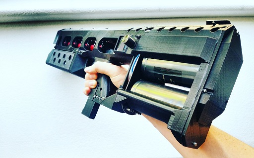
Fig. 4. EMG-01 coilgun (from https://arcflashlabs.com). Authors write on the corresponding page that they applied 25.2 V LiPo in combination with 360 000 mkF cap battery to drive the coils ("battery direct drive" abbreviation is used which is not completely correct, as we see).
Our calculation shows that these constructions have a high potential of development.
Sincerely Yours, Eugen.
| |
| Views: 692 | | |
| Total comments: 0 | |