| Home » Articles » Experiments » Other |
The other day I finished the mounting and testing of the latest version of my voltage converter for the coilgun, in which I tried to embody all my theoretical and experimental research of recent years. I described the procedure for its development in several videos on my YouTube channel (links are given under the text of the article). Here I will briefly outline the basic principles and report the results. So, the goals were: a) voltage converter powered by lithium batteries in the range from 7 to 25 V (which is achieved by "decoupling" the logic and power supply into two independent circuits), as compact as possible; b) the output voltage (maximum voltage on the charged capacitors) up to 450 V, with both positive and negative outputs in respect to the "ground"; c) the ability to work with any nominal values of the charged capacitance; d) protection against idling and output short circuit; e) the ability to control the operating mode from an external MCU; e) an advanced system for indicating the status of the converter (both with the help of LEDs and with the error signals to output ); g) the use of a standard (not "do-it-yourself") transformer.
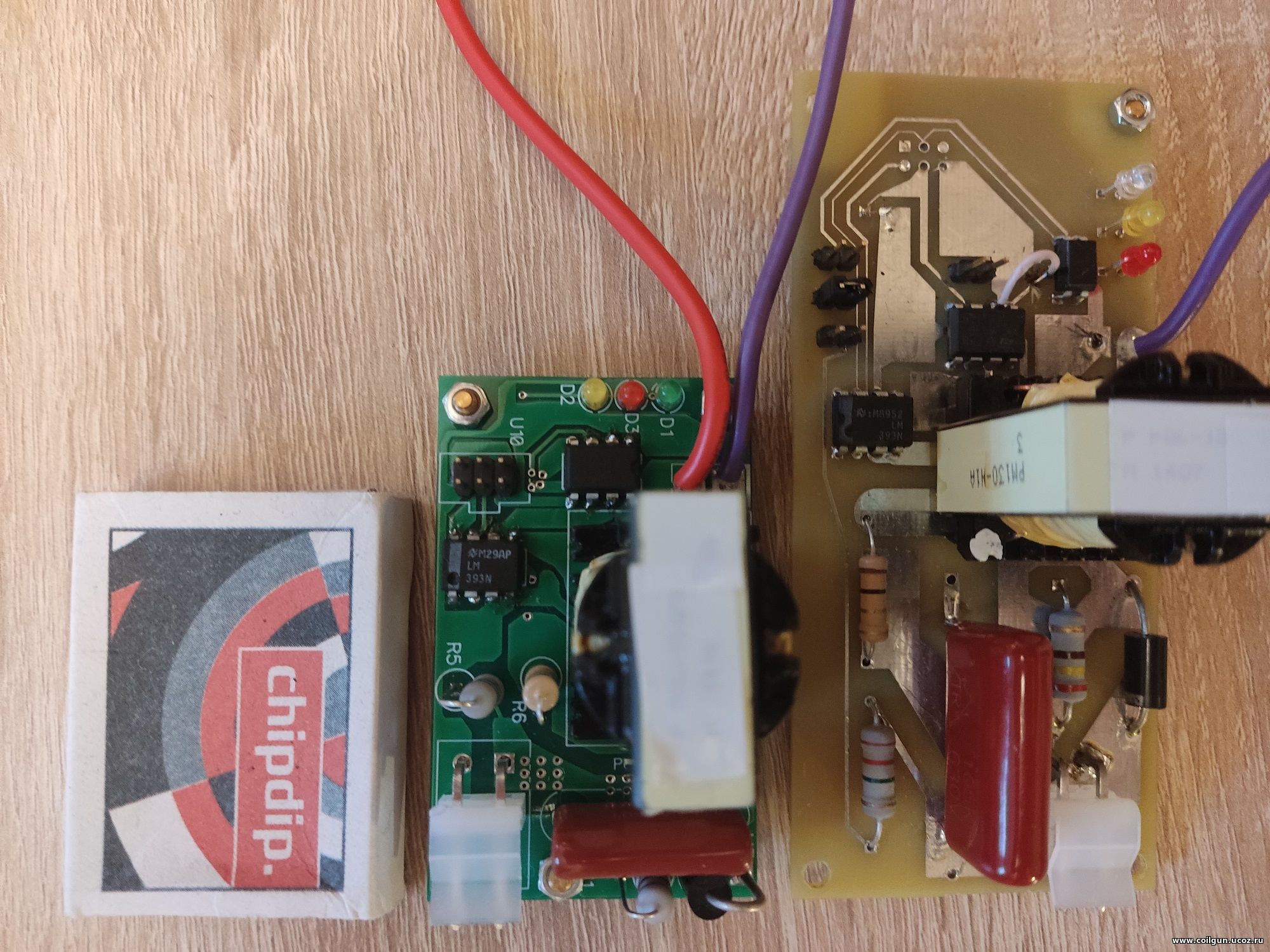
I note that the requirements of points (c) and (d) favorably distinguish this converter from the widespread simpler schemes such as Waldemar or flyback converters on 555 timer, which are so loved by beginners. They can only be performed using the control of the instantaneous current in the secondary winding. This, of course, complicates the design, but, in my opinion, it is a necessary thing if there is no desire to repair the converter every time after you forgot to load it, confused the polarity of the charged caps or decided to connect a couple more steps to their gauss gun...Well, to fulfill item (b), I had to design a converter in two versions - with positive and negative output - the circuitry is too different there.... On the photo below from top to bottom: a matchbox (to represent the size of the products), the final version of the converter, and its development version.
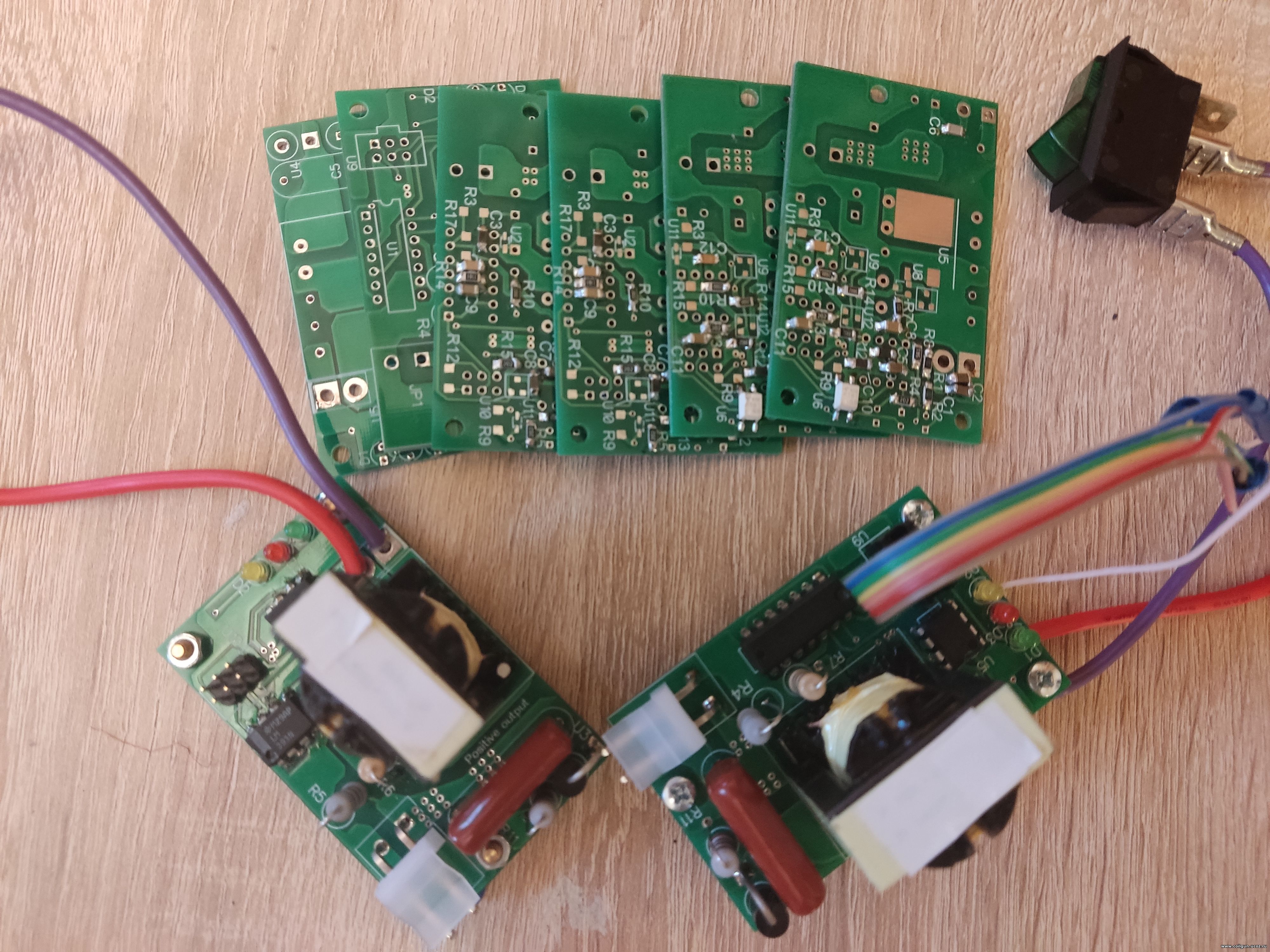
The design, in my opinion, turned out to be very successful, so I ordered several copies of PCBs at once - I will use them in the further coilguns. In the next photo, there is a converter in two versions (with negative and positive output), and boards for soldering future copies.
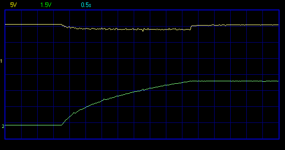
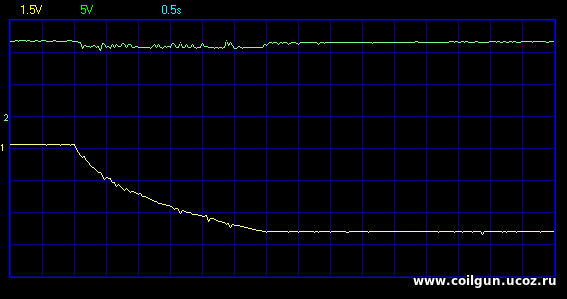
In the process of debugging the circuit, I took several measures using a digital oscilloscope. The figure below shows the oscillograms of charging the test battery of electrolytes with a total nominal capacity of 3290 µF to a voltage of about 425 V (got from the voltage divider 1:100, scale 1.5 V/div), and the supply voltage from the Li-Po 3S 1300 mAh battery (scale 1.5 V/div).
As you can see, charging takes exactly 4 seconds, while the voltage drawdown on the battery is about 1 V, which indicates a fairly significant current load... Taking this data as a basis, I calculated the instantaneous power of the converter. This is not as easy as it seems at first glance - the problem here is measuring large (up to 30 A) and rapidly changing currents in the primary winding, which does not allow using traditional methods with current-sensing resistors. You can read more about these troubles on the Arsenal Forum here, but I figured out how to get out of the situation - you need to measure not the input, but the output power of the converter - after all, we are, in fact, interested in it. It is important to us how quickly the capacitor is charged, and not how much energy is "pumped into the input" (after all, the efficiency of a properly designed converter is in any case close to 80...90%, and with a strong desire, you can always estimate the input power). You can calculate the output power using the following trick. We know that the energy of the capacitance C charged to voltage U is E = C·U2/2. Differentiating this formula by time, we find the energy derivative (which, in the absence of other losses, will be the output power of the converter): P = dE/dt = C·U·(dU/dt). The expression in parentheses represents the rate of voltage change on the capacitance, which can be easily determined using the logs of a digital oscilloscope. In fact, everything turned out to be a little more complicated, because the received signals had strong distortions due to interference (this is a normal phenomenon for the flyback converters). The final dependencies after mathematical processing are shown in the following figure (for convenience, they are brought to a single reference point along the vertical axes).
As can be seen, due to the noise of the signals, the calculated value of the output power (it is output by a gray curve) has significant distortions even after averaging. Nevertheless, we can confidently say that it has a value of about 75 Watts. A similar figure is obtained if you simply divide the total energy in the output capacitors by the charging duration - an interested readers can do this simple calculation on their own.
Update from 23.03.2023: after a slight variation of nominal values of the elements in the frequency-setting circuit of the converter, it was possible to further increase its power and achieve a charging duration of only 3 seconds. Here is the charging waveform for the negative output version:
Best regards, P.S. And here are the video to learn the development procedure of the converter: | |
| Views: 119 | | |
| Total comments: 0 | |