| Home » Articles » Experiments » Other |
Introduction. In my latest calculations considering projectile speed limitations in reluctance accelerators of different constructions, I concluded that one of the main such factors, especially for small-caliber coilguns, is the ohmic heat of the accelerating windings. This problem was not of a major role while portative accelerators had low energies, but it becomes significant as more powerful and high fire-rate constructions have apeared. In this article an experiment is described which was arranged to investigate heating and cooling of coils in conditions inherent to the typical portative coilgun launchers.
Problem setting and description of the experiment. Four coils were made for the investigations, their parameters and photos are on fig. 1.
Few words must be said about why such samples were chosen. Let us imagine a process of heat dissipation in a winding at high power short current pulse. As the process has very low duration (of order and less than a millisecond), a heat transfer to the environment may be neglected, and all the energy deposited stays confined in the coil (such a process is called adiabatic in physics). Provided the energy is higher than a certain limit (defined by a heat capacity of the winding), the copper melts and the wire goes down (or its insulation is damaged which is a kind of failure mode, too). That is the approach which I used to assess the energy capacity for a single-shot coilgun in the before-mentioned articles. Obviously, relatively "thick" coils will be more enduring than "thin" ones as they have more copper mass. Further, if the heat dissipated is not enough to destroy the coil, a cooling phase begins, i.e. heat transfer to a surrounding medium. If however the next shot occurs before the temperature of the coil falls to a safe limit, the damage may happen even if the energy threshold has not been crossed after the previous pulse. This situation is apparently the case for high-firing-rate coilguns with a moderate or even low energy of an individual shot.
Fig. 2. Illustration for overheating of the coil at one-shot (left) and multi-shot modes.
These uncomplicated suggestions show that it is critical to know such a parameter as heat trnasfer rate to build high-power and high firing-rate coilgun systems. Let us designate this value as k. Its dimension is Joule/sec (J/s). It's clear that the rate of cooling will be in some proportion to a relation between k and mass (more exactly, heat capacity C) of the coil. What will be the factors influencing k in a specific situation (coil) ? First, as the heat transfer occurs through an outside surface of the coil, the area of the winding (its size) will matter. Second, the dependence on the surrounding media and its parameters must occur, so I performed another part of the experiment with the coils immersed into epoxy (this approach is close to conditions which take place in some electromagnetic accelerators, for example my EM-3). Forced air-flow situation also falls into this category, and a lot of data can be found in special literature on this question. It would have been easy to include such an investigation into my plan, but I didn't do it at this work. At last, it will be useful to examine such a parameter as wire gauge. What can be its significance? Let us imagine how the coil cools down. Obviously, its outer layers will be chilled faster as they are closer to a cooling medium (the same can be said about the inner layers as they conduct heat directly to a barrel or a frame which the coil is wound on). So, we can expect some distribution of the temperature to form with its maximum in a depth of the winding (fig. 3).
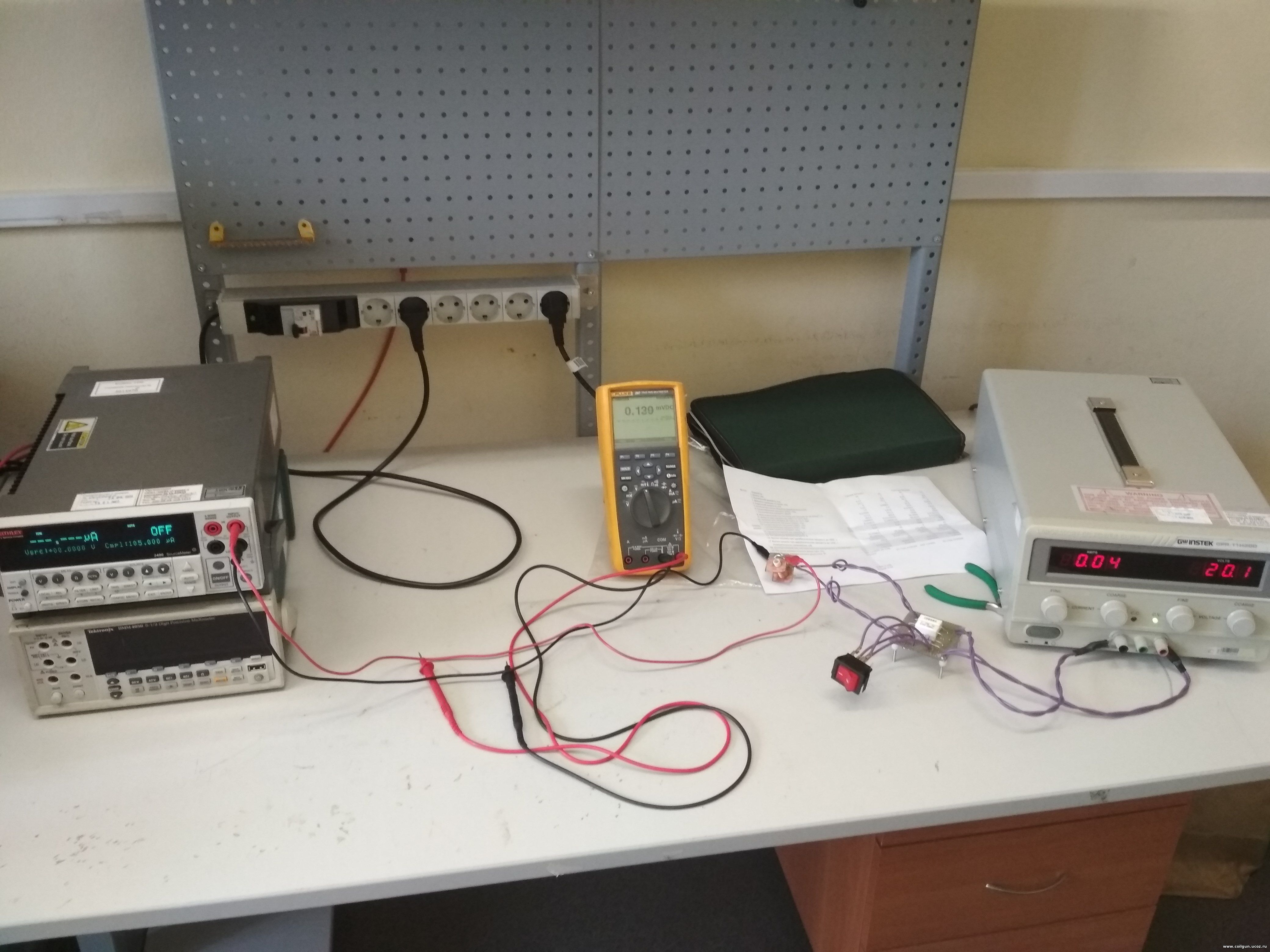
The heat from this depth can be delivered by two ways: along the wire (i.e. tracing the path of electrical current), or directly through the winding layers and inter-layer insulation. Provided the first mechanism to dominate, a coil wound with few turns of high-gauge wire will cool much faster than one of the same size but containing many tutns of the thinner wire. In this case, cooling rate would be in the same relation to the diameter of the wire d as the electrical conductivity (as thermal resistance and the electrical one R are both in inverse proportion to the square and in direct proportion to the length of the conductor). Here, it can be shown that R ~ d -4, i.e. this dependence is very strong. Conversely, if the "direct" transfer prevail, we will not see the dependence (or it will be much weaker). Cooling rate here should be in proprotion to the surface area of the coil as it limits the heat transfer to the medium. Basing on these suggestions, two diameters of the coils were chosen for the experiment - "thick" and "thin" one, both manufactured in two types wound by two different wire gauge - 0.6 and 0.22 mm per Cu. All the coils have the same length (20 mm) and caliber (inside diameter, 7 mm) which is close to what is now used in amateur coilguns. A short term (3..6 seconds) commutation to a power source through a simple toggle switch was used to heat the coils to an appropriate temperature. The temperature was controlled by measuring the DC resistance of the winding by forcing a test current of some fixed (few miilamperes) value. Power resistors were connected in parralel to the switch to ensure those current from the "heating" power source when the switch is open. A reverse biased diode was inserted in anti-parallel to the investigated coil to prevent an inductive peak to damage the toggle (see fig. 4).
Fig. 6. Example of the mesured signal.
What can we see on fig. 6? Before the switch is closed, the signal is constant and equals to U = I·R where I is testing current, R is winding resistance at room temperature. After a short period of exciting voltage fed, the toggle is off again and the coil starts to cool down, then its voltage drop can be written as I·(1 + α·∆T)·R, where ∆T is temperature difference between the initial temperature of the coil and the room one, and α is temperature coefficient of resistance for copper, which is known to be about 0.0043 1/ºC. The equations above can be used to determine the temperature of the coil, and waveforms - to calculate k constant which was talked about earlier. Remark: R and T here are suggested as some "mean integral" values along the winding which are perceived by a power source (real distributions may be very uneven, see before).
Experimental results and processing. Graphs like shown on fig. 6 were obtained for each "naked" coil at first , and then for epoxy-molded ones. Then k value was planned to be calculated from Newton's law of cooling:
Here ß is coefficient of proportionality (basically related to the heat transfer area S), ∆T is thermal difference between the coil and its surrounding. From these law, having solved one differential equation, one can obtain a relation for the temprature of the chilled body:
where Tokp. is surrounding temperature (suggested to be room one), T0 - initial temperature of the coil at the onset of cooling, τ is cooling time constant. It can be demonstrated that τ = C/ß, and
where dT/dt is derivative of the coil's temperature on time (i.e. cooling rate), and C - its heat capacity (it can be easily calculated knowing the mass of the coil and copper specific thermal capacity, which is well known). According to (2), the rate of cooling follows to exponential decay. However, processing of the experimental results has shown that they hardly fit to that law (see fig. 7). The strongest divergence from the exponent occurs in a final stage of the process when ∆T is small. I.e. the coils cools down rapidly at first, and then a long "tail" occurs. Remark: explanations of such dependence consists in uneven temperature distribution inside the winding (spoken before), which makes eq. (1) description too simplified. Exact thermal behavior of each winding can be obtained by numerical modelling and there are some works dedicated to these simulations especially for coilguns (see for example H.Chen et al, "Temperature Distribution Analysis of a Switched Reluctance Linear Launcher", IEEE Trans. on Plasma Sci., Vol. 41, No. 5, May 2013). Moreover, a "free" approximation (without fixing its parameters) leads to distortion not only of the exponent, but of the final temperature, too (and it is a priori a room temperature, 25°C).
Fig. 7. Dependence of voltage drop on cooling coil at constant testing current (Signal) on time (Time). Black squares are the exerimental points, red curves - attempt of approximations by exponents with different parameters. The latter can hardly be used for the whole experimental range.
So, each curve was approximated 4 times: "freely" (i.e. all dots "as they are"), with fixed threshold (i.e. with the final temperature forced to 25°C), and the same two for the first 10 data points. Cooling time constants extracted for the initial data range are marked green in Table 1, and initial temperatures T0 tabulated from eq. (1) (i.e. the temperatures before the cooling begins) are yellow. These values are most useful for the fufther analysis (see below).
Table 1. Experimental results for the coils without epoxy (upper table) and epoxy-molded (lower one).
It is clear that τ's obtained by different methods range in more than an order of magnitude. So it is a big question what of them is "true". In fact, the temperatue reached in our experiment is substantial but far from what can cause a damage of the insulation (it needs about 300°C), and much more less than melting point of the wire. I.e. real failures will occur at much higher heating. But, approaching to these temperatures, the rate of cooling will increase, and values of τ will be smaller than ones got in the experiment because of the above-described deviation from clearly "exponential" form of the signal. Thus, although an overall cooling is rather slow (see fig. 6), its primary decrease from "dangerous" thermal region will be very fast. In such situation it is reasonable to choose minimal obtained values of τ (these are green marks in Table 1) to assess a "durability" of coil. To explore a mechanism of heat transfer to medium, mean values of τ were calculated and plotted in a graph, together with electrical resistances and relation of the heat capacity and area of each coil (according to explanation below eq.2, the latter value should correspond well to cooling time constant). Fig. 8 illustrates the results of this procedure. For the convenience, all the numbers are normalized, i.e. divided to one for the first coil.
Fig.8. Normalized values of τ, R and C/S for the investigated coils.
It is obviuos that time constants correlate much better with C/S, than with R, as the classical theory does predict. Thus, it can be concluded that the main mechanism of heat transfer is "through the layers" to the outside area of the coil, not "along the wire" one. At last, heat trasfer rate k was assessed for each coil from eq. (3) for the maximum temperature obtained in the experiment (i.e. at the beginning of cooling process). Table 2 shows the results.
Table 2. Cooling rate for the coils under test (without epoxy).
Heat transfer rate is in range of 4..20 J/sec for the coils under experiment. Having got these values, it is possible to evaluate a firing rate of a specific coilgun provided an energy deposition for its coils is known. For example, EM-3 "Electric bow" coilgun with its windings close to № 3 or 4 by parameters, would be able to make 1 shot per 7 sec while keeping the temperature of its coils about 100°C.
Conclusions.
1) Cooling time constants for the investigated coils are 5..12 sec for the highest temperatures reached in the experiment. As a coil cools down substantially during ~3τ, we may state that for a powerful coilgun of about 7 mm caliber working closely to a thermal limit (i.e. with coil(s) heated nearly up to the damage point), it is inexpedient to maintain capacitor recharging time of less than ~30 sec. 2) As expected, "thin" coils cool down quicker that "thick" ones, but the rate of cooling is not proportional to the coil's heat capacity (mass). On the contrary, the rate correlates well with the ratio of heat capacity to the area of the coil. Basically, it can be said that "thick" coils cool down twice slower than "thin" ones. 3) Wire gauge has only slight influence on the cooling rate which (in combination with the previous clause) means that the main mechanism of heat transfer is "through the layers" to the outside area of the coil, not "along the wire" one. Hence, it is possible to choose parameters of high firing-rate and powerful coilguns on the basis of their demanded electrical properties only (otherwise, it would be preferable to use low-voltage systems with thick wires to accelerate the cooling process). 4) Heat transfer rate is in range of 4..20 J/sec for the coils under experiment with temperatures about 100°C. Having got these values, it is possible to evaluate a firing rate of a specific coilgun provided an energy deposition for its coils is known. 5) Epoxy molding has an ambivalent effect on the heat transfer. "Free" approximation of the initial region of the coooling curve yields some deceleration of the process, but there's an opposite result in all other cases. Anyway, the cooling rate changes no more than doubly, i.e. without any dramatical shift.
Sincerely Yours,
| |||||||||||||||||||||||||||||
| Views: 529 | | |||||||||||||||||||||||||||||

| Total comments: 0 | |