| Home » Articles » Theoretical papers » Coilgun calculations |
Lately, more and more constructions of the DIY coilguns have been being developed which utilize the simplest SCR+coil+cap circuit in each stage. They are quite powerful due to high capacitance used (for instance, this specimen reaches more than 100 m\s for the first time in RuNet), and modern material treatment methods help to get nice outlook and ergonomics. Along with an essential respect to the authors, some sadness may be reflected, as the gauss-building is evolving by the most primitive way - increase of the power and capacitor weight, without, for example, any effort to develop a commutation scheme. This method is most effective from the point of view of labor expenditures (one should just add more and more capacitors and stages with power SCRs), but it is clearly futile in using all the opportunities inherent to the principle of the electromagnetic acceleration. In this article I will try to analyze some limitations of the SCR-driven coilguns. and their influence on the main output parameter of the accelerators - projectile velocity. The method of the analysis is based on correlation between a geometry of acceleration coils and a form of driving current - in full similarity to the technique used in my previous paper dedicated to the investigation of accelerators with identical coils.
1. Basic assumptions. 1.1. An optimal current form for gauss-gun. It is known that current waveform in thyristor-driven overdamped RLC-circuit is a single fading pulse (see fig. 1(a)). The moments are accented on the picture when the current reaches its maximum (tmax), and when a geometrical center of a projectile passes the center of coil (t0) - so called "zero point" (ZP) - magnetic field is braking the projectile from that time ("suckback" effect). In contrast to closeable-switch-driven systems, there is no opportunity to inhibit the drive on an appropriate time (or in an optimal projectile position, accordingly), so the current has to decrease substantially up to t0 for the suckback to have no considerable effect. From another side, we know that an accelerating force has its maximum shifted closely to ZP (see fig. 1 (b)), so the current must preserve a significant value when the projectile is passing the corresponding zone.
Fig. 1. Current waveform in a coilgun curcuit (a) and typical accelerating force vs projectile position dependence (b, taken from here).
Thus, we may consider two hypothetical cases (they are marked on fig. 1 with dashed lines). First of them (marked red) implies a prolonged current pulse with its maximum when the projectile is nearly in ZP - the body is as well accelerated here as braked immediately after, with a total efficiency becoming close to zero. This situation occurs in high-resistance and high-inductance circuits. The second opposite case (highlighted blue) considers the inductivity to be so small, that the current is reaching its peak value long before the projectile is in ZP, and decaying slowly afterwards. It is clear that the system is not optimal here, too, because any coil containing more turns would be more effective as it could put more accelerating force to the projectile on a more appropriate moment. So, we have to conclude that some medium case would be the most efficient which is marked green on the fig. above. FEMM modelling and practice show that the most optimal current form would have the tail reducing in ZP to about 1/3 of its maximum (i.e. i0 ≈ 1/3 imax). 1.2. "Critical damping" regime as an optimal mode for projectile acceleration. It is shown in [1] that there are two main types of RLC-circuits in a coilgun: "overdamped" and "underdamped". In the former one, a resistive-capacitive constant RC/2 is more than inductive-resistive 2L/R one, and vice versa in the latter. The current-voltage waveform is periodic in the free underdamped circuit and leads to charge reversal in a cap, which is unappropriate for a portable coilgun with its electrolytic capacitors, so this mode is avoided by placing an antiparallel diode across the cap - it blocks the back voltage, but induces a long current "tail" which brakes the projectile effectively. Thus, the underdamped circuit is irrelevant for the reluctance coilgun. Strongly overdamped system is, from other hand, ineffective, too. The fact is that magnetic field is formed not by a capacitor or active resistance, but by a winding. So, a small value of 2L/R (i.e. small inductance) means accelerating force to be negligible. Both cases mentioned are illustrated on fig. 2.
Fig. 2.
So, the most effective circuit is expected to have high inductance, but without going to the underdamped mode. Such a system occurs when RC/2 equals to 2L/R and corresponds to "critical damping". It also satisfies the demands of the previous section about maximum shifting of the current maximum to the right along with its fastest decay. Thus, for the exploration of the maximum velocity achieved in a portable accelerator, it is enough to analyze critical damped system, because it is expected to be the fastest one.
2. Problem setting. Let us translate the speculations above to a language of mathematics. It is demonstrated in [1] the the current form in the critical damped system follows like
where U0 is initial cap voltage, R is active resistance, and
It can be shown easily that maximal current in this chain is given by imax = 2U0 ·exp(-1)/R ≈ 0,736·U0/R (2) , and occurs on the moment
Acccording to (1)-(3) equations and value of current in ZP i0 ≈ 1/3 imax (see previous section), it is easy to calculate the time t0 acceptable for the projectile to pass the ZP: t0 ≈ 3 tmax (3)
If we consider the coil to have the length of l, and current to be switched on when projectile is entering the coil, then the projectile has to make a path of l during the time assigned by (3). Thus its maximum velocity can be easily obtained by
As shown in [1], the inductive constant of a coil depends only of its geometry, namely:
where a is density factor of the winding (i.e. relation of the wire core's diameter to its diameter in an isoltation, usually a ≈ 0,85), d and D - inner (caliber) and outer diameters of the coil, p - resistivity (1,75·10-6 Ohm·cm for copper). Thus, the maximum achievable speed in SCR-driven coilgun is determined only by the geometrical properties of its windings. So, out task is deduced to assessment of vmax basing on the analysis with (4) and (5) relations of coil forms utilized in coilguns.
3. Solution. Tables of solution of (4) and (5) for vmax for different calibers d are resolved in fig. 3. The range of lengths of a coil, like in my previous paper, is in the limits from l = d to l = 4·d (longer coils are ineffective according to FEMM modelling and lot of experimental data), and outer diameters are from D = 1,1·d to D = 2·d.
Another note is that
The task is not so easy as earlier, because we have no "coil identity" circumstance here - the windings can be different now, and their quantity is limited by a barrel length only. It appears that it gives more efficient acceleration when some of the coils (situated in the beginning of the accelerating path) are "thicker" and driven by more capacitance than other ones (mounted closer to the end), which should have less diameters and commutated to smaller caps. Remark: it is considered by default that all the coils have the same length (it is sensible because they must comply to a single projectile of fixed geometry). Besides, one common initial voltage for all driving capacitors is assumed for the reason of practice. Considerations above are illustrated on fig. 4 and agree completely with the conclusions of sec. (1) and (2) - a winding situated in the beginning of the accelerating path has longer interaction with a projectile, so it must have larger inductive and capacitive constants, in contrary to the last coils.
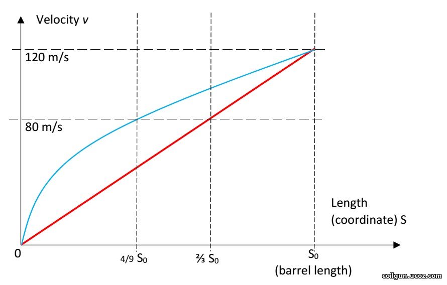
Fig. 4. Schematic picture of multistage accelerator with its current waveforms. It cannot be said at once what coil will be more heated here - the thicker windings have higher thermal capacity, but more dissipated power, too. Let us appeal to common sense and mathematics. First, a part of total energy wasted on a specific coil has to be determined. To do this, we have to know two laws: 1) How does the effeciency of acceleration change (in relation to a mean value) in dependence on a stage number? 2) How is the projectile accelerated (i.e. what part of total kinetic energy must be obtained on each stage)? The analysis may be performed for the first and the last stages only - it's reasonable to suggest that a situation would be some median for all other coils. The efficiency-vs-stage dependence can be assessed according to my own experience in SCR-driven-gauss-building. For instance, EM-3 system has the efficiency for the first stage 1,7 times smaller, and for the last one - 1,6 times bigger than the mean integrated efficiency. As for the law of acceleration, we may state that it occurs in a range between two models: uniform acceleration (which means a constant accelerating force put to a projectile), and linear velocity change (which implies equal speed increment on each stage). These models are depicted on fig. 5.
Fig. 5. Acceleration scheme in a coilgun: unformely accelerated (blue) and equal velocity gain per stage (red).
Suggesting a total length of acceleration to be S0 (like on the picture above), and projectile exit energy Emax = m*vmax2/2 (where m is projectile mass), it easy to demonstrate that energy increments for the first and last stages for the mentioned models are:
Picking some median values between ones shown in the table, we can get: E1 ≈ Emax*(l/S0)1,5 EN ≈ (Emax *l)/(1,5*S0) Now, to converse these values to heat dissipation in coils, one should assess a total efficiency of acceleration. As earlier, it was suggested to be about 8% for caliber d = 8 mm and proportional to a caliber (this value is confirmed by FEMM modelling). A calculation of the peak temperature was conducted for the coils with parameters depicted in fig. 3, accounting for the heat capacity of copper 0,4 J/(g·°C), initial temperature 25ºC and acceleration path 60 cm (this seems to be close to maximum for a portable construction taking into account an additional place needed for sensors and other constructive elements situated along the barrel). Then, a limit was suggested to be exceeded if the temperature rose higher than 300 °C - this is a point when heat-resistant electrical varnish loses its isolating abilities. As a strong tension occurs in a winding during a shot, the short circuit is expected in such situation. Those cases are colored by red in fig. 3 and limit vmax in two most high-speed systems of 3 mm caliber. As a result of the calculation, it apperas that the most heated coils are the thinnest ones, situated on the end of barrel (in contrast to a transistor-driven coilgun).
2) Weight of the power capacitors. State-of-art electrolitic capacitors have some boundary energy accumulated per unit of mass, which varies depending on a specific type of a cap, and makes about 3 grams per Joule. Thus the maximum energy spent per shot is about 2000 J (this corresponds to the capacitor mass of 6 kg - clearly close to a limiting value for a portable system). Comparing this number to the projectile muzzle energy corresponding to vmax from fig. 3, and taking into account a priori efficiencies mentioned above, we can get a range of velocities in which the energy capacitance of the system doesn't exceed those limits. This crossing would obviously take place for long heavy projectiles having maximum velocity. These "exorbitant" values are marked blue in fig. 3. They correspond to situations when vmax can be achieved in stationary systems only (unless it doesn't contradict to the previous section about heat dissipation).
3) ESR influence. An internal resistance of the capacitor Rint (a.k.a. ESR = equivalent series resistance) is believed to be the main limiting factor for the SCR-based coilguns. Indeed, while the projectile is being accelerated, the caps have to discharge faster and faster, so the windings are to be made of lower and lower resistance (i.e. wound by a thicker wire or/and contain less turns). Sooner or later, a moment occurs when resistance of a coil becomes comparable to Rint, and from now the capacitors begin heating themselves more than accelerating the projectile. Obviously, this situation is of the highest importance for the last stage, where vmax is being achieved, and which parameters were used in fig. 3 tabulations. It is known that Rint is approximately in inverse proportion to the capacitance for a given technological series of electrolytics: Rint*С ≈ const. This simple fact will help us if we remember that a "critically damped" system is considered:
The inductive constant was implicitly calculated for fig. 3. Its values for 3 mm caliber are shown in fig. 6.
Fig. 6. An example of calulation of the inductive constant for the last stage of 3 mm-bore system. Eq. 6 leads to Proposing maximum Rint ≈ 0,5*R (this border is arbitrary, but FEMM simulations confirm that the substantional decrease of acceleration efficiency begins from ESR approaching 30...50% of winding resistance), and basing on the equations above, we get a simple formula for Rint doesn't exceed the permitted limit:
Thus, the only thing left is to determine the ESR constant of the caps. I conducted some experiments with Jamicon, Samsung and EPCOS electrolytics and got Rint*С ≈ 20 Ohm*microFarads. This value is minimal seen in experiments, so, using it, we will obtain an optimistic assessment for vmax. So, we have to reject all the coils with inductive constant less than 20 mcs. All configurations under this restriction are colored yellow in fig. 3 and 6. It is clear that small caliber systems suffer the most. So, it can be concluded that ESR is a strong limiting factor for them, indeed.
5. Results and discussion. Following conclusions can be made from the results of fig. 3. 1) On the assumption of the geometrical properties of multistage SCR-driven accelerators, theoretical velocities up to 200 m/s are achievable for the calibers of less than 8 mm. The highest-speed caliber is about 5 mm. 2) The obstacles on the way to higher speeds are overheat of the coils and (mainly) ESR of the capacitors for small-bore coilguns, and huge mass of the power capacitor for large-bore ones. For 20 mm and larger calibers velocities of more than 80 m/s cannot be obtained exclusively because of geometry of the coils (even without the "weight" limitation).
It is clear that small calibers are the most attractive for breakthrough to high velocities. Such a conclusion is not very encouraging from the constructor's point of view, because the less is the caliber - the more stages (and thyristors, and sensors and so on) we should mount to preseve the same acceleration path. A way how to avoid ESR-limit is also unclear - perhaps, it will be overcome when new technologies of the electrolytics, or new types of capacitors themselves appear. Nevertheless, it can be concluded that a potential of SCR-driven portable multistage electromagnetic accelerators is not yet exhausted, and one may expect for new and new constructions to be projected and demonstrated soon...
Literature. [1]. http://coilgun.ucoz.com/Mathematics_of_a_coilgun.pdf
Sincerely Yours, | ||||||||||||||||||||||||||||||||||
| Views: 739 | | | ||||||||||||||||||||||||||||||||||
 is above mentioned inductive constant (it equals to the capacitive constant
  by the terms).
| Total comments: 0 | |