| Home » Articles » Experiments » Other |
To switch the accelerating coils in a gauss-gun, power semiconductor switches are used - MOSFETs, insulated gate bipolar transistors (IGBT) or thyristors (SCR). From the point of view of control, thyristors are the simplest, and for them I once developed a couple of driver circuits (combined with optical projectile position sensors). Concerning transistors, the situation is more complicated - you need to apply a constant voltage of a certain amplitude from a source with a low output resistance to their gates. For this purpose, specialized driver chips are usually used (many of them are produced, for example, by Infineon). These ICs are available on the market in a wide variety, including drivers of upper and lower channels, with direct or inverse input, single- and dual-channel, etc.The only problem with them is their high price, which becomes especially noticeable if we are talking about a multistage accelerator. This nuisance can be overcome if you use the very widespread IC 555 timer as a driver. This chip is known to every electronics engineer and produced by many companies under various names. Some of them are shown in the table below:
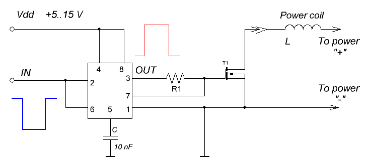
The principles of operation of this IC are described in many places, and here I will not dwell on this, only note that it has a significant (up to 200 mA) output current and is very cheap, which allows us to use it for our purposes. The first figure shows the circuit for turning on the timer as a simple MOSFET or IGBT transistor driver. In this case, the signal at the input goes to the output with an inversion (i.e., to get a high level at the output, you need to apply a low level to the input). The value of the resistor R1 can be in the range of several tens to several hundred ohms, depending on the gate capacity of the key used (the more "heavy" gate, i.e., the more powerful transistor T1 we use, the lower the nominal value of R1 should be). In low-power circuits, it is possible to use MOSFETs with logical switching levels (for example, the IRL... series), then R1 is better to be even smaller, and the supply voltage can be reduced to 5..6 V (in this case, the timer can be controlled by signals directly from the output of a 5-volt microcontroller). When using conventional switches (which have gate threshold voltage of 2 to 4 V), it is better to use at least a 10-volt power supply.
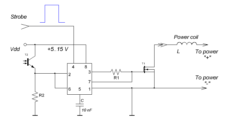
A special feature of the circuit is its high noise immunity (a level drop of at least 2/3 Udd must be applied to start) and increased driveability (for this purpose, output 7 with an open collector is used, connected directly to the transistor gate). The second figure shows the timer control circuit from an optical sensor, which can be a photodiode or phototransistor. In this case, when the sensor is shaded by a passing projectile, the output voltage drops sharply, which starts the timer. If the phototransistor is used as detector (as in the figure), then the nominal value of R2 can be from ones to tens of kOhms, the sensor being the photodiode - from tens to hundreds of kOhms.
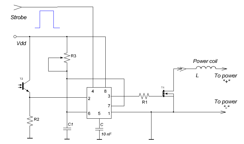
Pin 4 here can be used for additional timer gating (for which a separate signal line can be provided, common to drivers of all accelerator stages). This may be necessary in the case when there is a fear that the projectile may for some reason linger in the barrel opposite the photo sensor for a time beyond the planned - then, if nothing is done, the whole charge from the main capacitor of our gauss-gun will "drain" through one switch, which can lead to its burnout or short circuit of the coil that it commutes (such a case is described by J. Paul). The situation will be even worse if we work with an electromagnetic accelerator powered directly from a battery - then the expensive accumulator can also fail... Therefore, in all my projects, I use a signal of one kind or another, strobing the operation of all stages, with a duration that obviously exceeds the duration of the acceleration of the projectile (about a tenth of a second). Finally, the last diagram shows the use of a timer as a monostable generator, triggered directly from the optical sensor.
This method of switching may be necessary if the switch needs to be opened for a time longer than the duration of the photodetector shading (for example, if the length of the coil is longer than the length of the projectile - this situation may occur in low- and medium-power accelerators). Here, when the sensor is triggered, the timer generates high-level signal with a duration of ~ 1.1·R3·C1 (if R3 is a potentiometer, then it can be adjusted). It should be noted that all of these schemes can also be used to control conventional thyristors.
| |||||||||||||||||||||||||||||||
| Views: 588 | | | |||||||||||||||||||||||||||||||
| Total comments: 0 | |


