In a previous article of this section we found out a following eqation for the acctractive force between the coil and projectile:
| F = Bнас ·S ·[H(x+ l) - H(x)] | (1) |
where Bнас is saturation induction of the ferromagnet, H - field strength at the front (with coordinate x) and rear end ofthe projectile (having a length of l), S - the projectile's cross-section perpendicularly to the magnetic flux.
From this relation it can be seen that the problem of optimizing the shape of the winding, generally speaking, should be solved together with the selection of the appropriate geometry of the accelerated body. However, for an organized presentation of the material, I decided to write two separate publications on these topics. Optimization of the shape of the projectile will be discussed in the next article, and here we will discuss the properties of the windings.
First of all, it is necessary to dispel a couple of tenacious myths, namely: about the significant impact of the gauss gun's voltage on its efficiency, as well as about the presence of a certain "wonderful" form of winding (different from the usual cylindrical one).
To begin with, let's deal with such a question as the influence of the supply voltage. Many novice gauss-builders for some reason believe that the higher the voltage their system has, the higher its efficiency will be. Some of them even construct monstrous devices based on Tesla coils (which, generally speaking, have nothing to do with electromagnetic acceleration). The other extreme is the fascination with low-voltage accelerators, which at their limit have the construction of gauss-guns powered directly from batteries - this type of coilguns was analyzed in detail here.
In fact, the supply voltage of the coilgun is a secondary parameter and only indirectly affects its properties. Let's imagine that we have a coil of fixed dimensions and supply it from a capacitor of half the voltage compared to the original one (but with the four-fold capacity, in order to leave the same energy of the system). It turns out that by choosing a wire diameter that fits 2 times less turns in the same dimensions, we will keep the same field strength and the rate of discharge of the capacitance. Thus, the efficiency of the coilgun will remain the same. Table 1 shows, for example, the parameters of such RLC-circuits, which are identical in terms of projectile acceleration.
 |
Fig. 1. Illustration of identity of RLC-circuits powered by various voltages (from here). |
It follows that the choice of supply voltage is dictated only by design considerations. So, its high value complicates the wiring of printed circuit boards, insulation of conductors and makes the process of debugging the structure very dangerous. For reference, at the time of writing this article, the maximum switching voltage for power switches available for free sale is about 1500 V, and the maximum voltage of electrolytic capacitors is 500 V (capacitors, of course, can be connected in series, but it already brings certain design difficulties to the circuit). On the other hand, in low-voltage systems, huge currents occur (see Table. 1), which requires the use of massive conductors and increased attention to the quality of connections. Experimets shows that the optimal voltage is few hundred volts.
Another common myth is that, unlike the usual rectangular coil (which is the simplest and most convenient for winding), there is some "magic" form of winding that can dramatically increase the efficiency of acceleration. The discussion of these wonderful coils began in the old forums and sometimes continues, but no evidence has been presented so far of a real increase in the effectiveness of the coilgun based on these forms.
 |
Fig. 1. Various gauss-builders' suggestions on optimization of the coil form. |
Sometimes researchers suggest an asymmetric coil shape in order to "stretch" the site of the increasing field (where the projectile is accelerated). However, it is obvious that the consequence of such deformation is an equivalent decrease in the retracting force acting on this spot, since the peak field (determined by the ampere-turns of the winding) when using such a coil "with a displaced center of gravity" either remains the same, or even decreases due to the deviation of its shape from the optimal one (which is defined here).
 |
|
| F1 ~ H(x2) - H(x1) | F2 ~ H(x4) - H(x3) < F1 |
Fig. 2. A schematic comparison of the efficiency of a "normal" cylindrical coil and a hypothetical asymmetric winding. The retraction area in the latter is larger, but due to a decrease in the retraction force F, the overall acceleration efficiency remains the same or decreases.
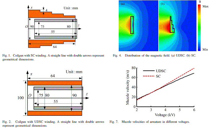
The only real case known by me, when the deviation of the shape of the winding from the cylindrical one gives some positive effect, is the approach proposed in the publication [1]. However, it concerns an induction type accelerator, and the achieved effect is very small (see Fig. 3).

Fig. 3. Illustrations from the article [1]. SC is a variable-diameter winding investigated by the authors (Fig. 1), UDSC - "traditional" coil (Fig. 2). Fig. 4 - field distribution, Fig.7 - the resulting output velocity of the projectile ("Muzzle velocity") depending on the supply voltage.
Thus, we will further consider only "ordinary" windings of rectangular cross-section.
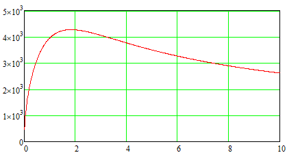
It follows from eq. (1) that the retracting force acting on the core is approximately proportional to the difference in the field strength at its front and rear ends. If we assume that the field at the front end is much stronger than at the rear one (this is true for almost the entire acceleration path), then we get a natural conclusion that we must strive to get the maximum magnetic field inside the winding to increase the efficiency of acceleration. Figure 4 shows the result of calculating the field in the center of the coil for a fixed power supply.
|
|
Fig. 4. The field strength (A / cm) in the center of a solenoid with an outer diameter of 3 cm, inner diameter 1 cm, wound with a copper wire with a diameter of 0.25 mm (the insulation thickness is assumed to be zero for simplicity). The current power is 1000 W. The length of the coil is plotted along the horizontal axis. |
As we can see, the maximum field is reached when the length of the coil is about 2 cm, then the field decreases. That is why it is necessary to manufacture coils for the accelerator in the form of relatively short cylinders. To obtain high projectile speeds, it is necessary to build multi-stage systems with a large number of individual coils, from which various design difficulties arise. In particular, the concept of a single long winding, which is often proposed by novice coilgun-builders, is not viable (Fig. 5).

Fig. 5. We need multiple-coil design to achieve high velocities.
On the other hand, very short, "pancake" coils, which are often used in induction accelerators, will also work poorly in coilguns. Experience shows that, in order to maintain an acceptable efficiency, the length of the coil should be held in the range of 2 to 4 of its internal diameters.
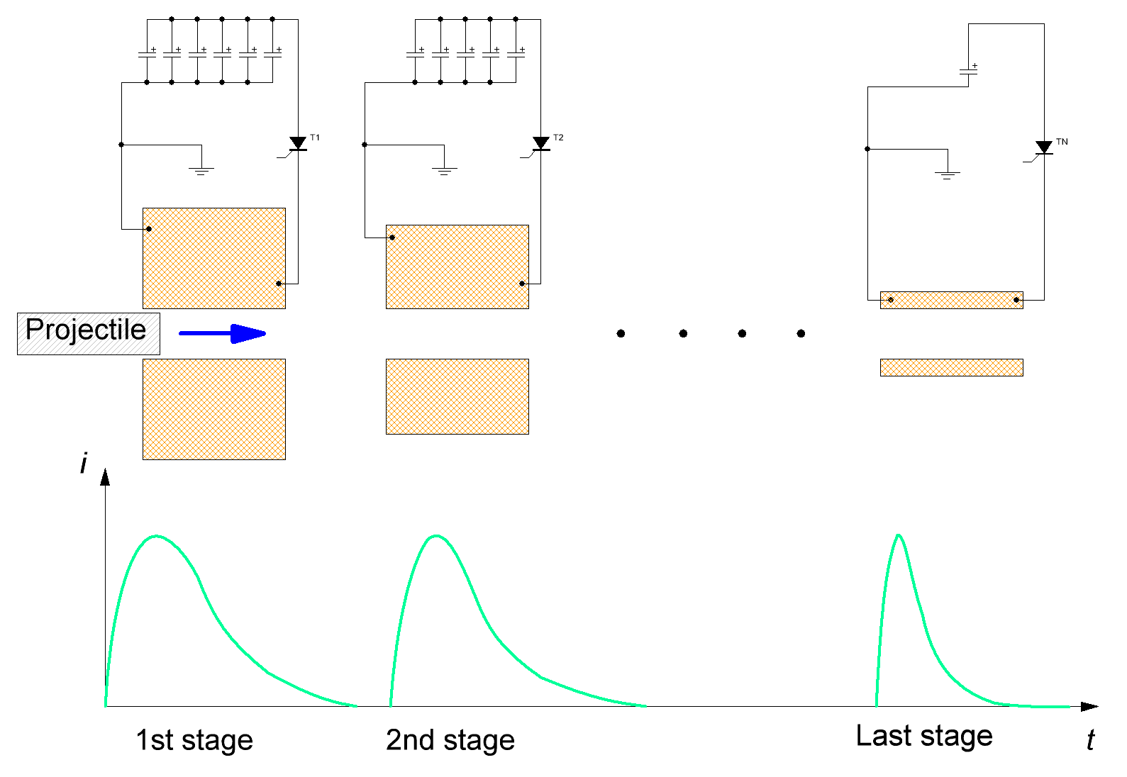
Turning now to the consideration of the thickness of the winding, we recall that at a fixed power source, the strongest field is generated in the center of the coil, the length of which is equal to two internal diameters, and the outer diameter is three internal diameters (such a coil is called "ideal"). This "ideal " coil should theoretically provide the maximum efficiency of a coilgun of any power and caliber, as well as at an arbitrary initial discharge rate. In practice, however, this is not the case - the fact is that in an electromagnetic accelerator we are not dealing with a constant current in the coil, but with a dynamic process, when the current must have time to grow to the maximum value during the movement of the projectile through the winding, and then decrease so as not to draw the projectile back. The shape of the current in this case depends on the geometric proportions of the winding (in addition, of course, to the electrical parameters of the external circuit). Namely: all other things being equal, the current in the winding decreases faster with a decrease in its thickness. On the other hand, it is also impossible to reduce the diameter too much, since the magnetic field and, consequently, the retracting force will decrease.
Thus, there is a certain compromise, and the process of optimizing the shape of the winding is best carried out for a specific case by numerical modeling (for example, in FEMM). The result is that winding with outer diameter less than the "ideal" forms are the most effective, and, if we are talking about multi-stage system, the optimum thickness of the winding decreases with increasing the initial speed of the projectile (see Fig. 6).

Fig. 6. Schematic view of a multistage coilgun with current waveforms in its coils (from here).
Another good example of a numerical experiment in which coils of different shapes were modeled is given on this page of the Arsenal Forum.
Summarizing the experience of modeling and experimenting with various coilguns, we can say that the range of external diameters of the coils that give the best acceleration of the projectile is from 1.2 to 2 of internal diameters (calibers) of the accelerator. In addition, when the thickness of the winding decreases from its optimal value, the decline in efficiency is much steeper than when it increases, and the same applies to the length of the coil (see Figure 4). That is, it is better to "make a mistake" in the direction of a larger coil when winding.
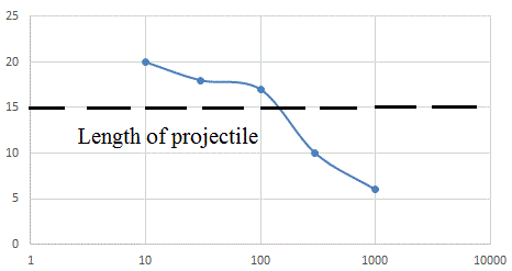
Finally, we will dispel another common misconception about the length of the coil. It states that for the best acceleration, the length of the winding must necessarily be equal to the length of the accelerated body. In fact, this is not always the case. Figure 7 shows the result of modeling the optimal shape of the coil for systems of different energy.
 |
Fig. 7. The dependence of the optimal coil length in mm (laid on the vertical axis) on the energy of the system with the following parameters: voltage is 450 V, the inner diameter of the coil is 10 mm, the length of the cylindrical projectile is 15 mm. An accelerator with an undisconnectable key (SCR) is modeled . |
| Capacitor energy, J |
It can be seen that with an increase in the energy of the accelerator, the optimal winding length decreases. It is, indeed, approximately equal to the length of the projectile in the energy range from several tens to several hundred J, but there are significant deviations beyond this interval.
Let's try to summarize:
1) The main parameter that determines the efficiency of the coil in terms of acceleration of ferromagnetic bodies is its geometric shape (length and outer diameter). The remaining characteristics of the system (supply voltage, wire diameter, etc.) are secondary and have only indirectly influence.
2) If the inner diameter of the coil is denoted as d, then the optimal length of the coil is in the range from 2d to 4d, and the best outer diameter is from 1.2 d to 2d.
3) In the energy range from several tens to several hundred J, the optimal length of the coil is approximately equal to the length of the projectile. At lower energies, longer coils are advantageous; at higher energies, shorter coils work better.
Literature.
[1]. Y.Hu et al, "Experiment and analysis on the new structure of the coilgun with stepped coil winding", IEEE Trans. on Plasma Science, vol.46, No. 6, June 2018, p. 2170.
| <Back | Next> |
