Introduction.
Lately, an accumulator-driven construction of the gauss gun has been widely discussed. Coilguns of Jason Murray may be distinguished among really built devices.
A main feature which differs this design from the “traditional” constructions is no need of charging of a power capacitor before each shot. Consequently, at first, building of voltage converter can be avoided. Secondly, the acceleration of the next bullet can be stated at once after the previous projectile leaves the barrel, and a theoretical fire rate is limited by a feeding system only.
It’s obvious that the main parameter of the accelerator – its output velocity – depends on pulse power output of the accumulators. So, the creation of this sort of coilgun became possible only after compact high-current Lithium-Polymer (LiPo) accumulators appeared.
In this article I will try to assess a maximum velocity reached in accumulator-driven gauss-gun (ADG).
1. Basic equations in accumulator-driven coilgun.
For the beginning, let us imagine the electric circuit of a single-stage ADG (fig. 1). One can see that a typical component of any coilgun – the capacitor – is absent, but an internal resistance of the accu (Rint) and parasitic resistance of the wires connecting the accu and accelerating winding (Rpar) are designated – they will play a major role in following analysis. The latter includes a resistance of a commutating switch (it is depicted as S). The winding resistance is RL.
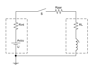 |
Fig. 1. Scheme of 1-stage
accumulator-driven coilgun
|
The accumulator is illustrated as a series connection of DC voltage source and its internal resistance, which is a simplified but close to true performance for LiPo accus in a pulse mode.
Thus, there is a simpler RL-circuit instead of the classical RLC one. Its current vs time evolution after S switch is closed is depicted on fig. 2. The current tends asymptotically to relation of the voltage to a total chain resistance R = Rint+Rpar+RL:
Imax = U / R (1)
«Time constant» of the current rise is usually included which is
τ = L / R (2)
in our case.
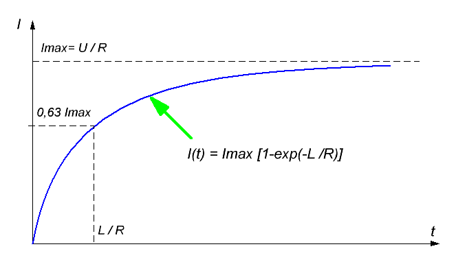 |
Fig. 2. Current waveform in RL-circuit. |
Current builds up to approximately 63% of its maximum value Imax during τ.
Then, as an accelerating force is in proportion to current, a pulse duration in a coilgun must be higher than τ to obtain a considerable velocity. So, it will not be a big mistake if we take Imax as the value of current in our calculations.
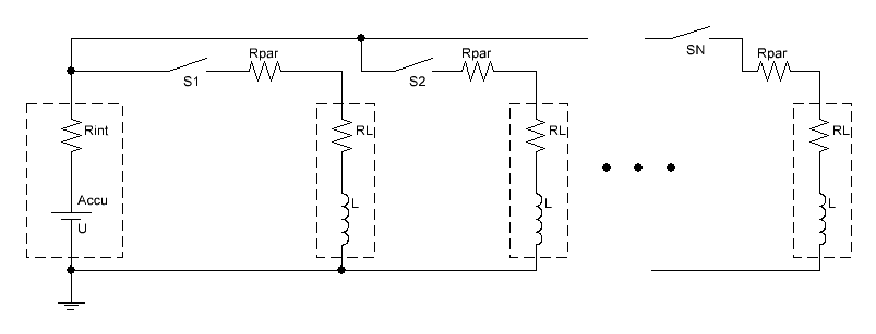
The same is true for a multistage system. Indeed, the multistage design is derived from the single-stage one by parallel connection of desired number of the coils to the power supply. For the simplicity, the coils may be considered the same with identical Rpar and RL parameters (moreover, that is true for J.Murray’s construction). Besides, they are usually switched in sequence, and each next coil is activated approximately on the moment when the previous one is deactivated. Thus, the current can be suggested something about DC with the value of approximately Imax (fig. 3).
 |
Fig. 3. The scheme and current waveforms of the multistage accumulator-driven reluctance launcher. |
The role of the accumulator is to ensure that current.
2. Equation for the projectile velocity.
Let us remind that the question we try to answer sounds like follows: what is the maximal output velocity of a projectile can be obtained in ADG using actual for today LiPo accumulators?
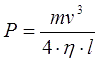
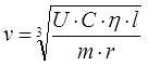
I have shown in this note that power necessary to accelerate a projectile of mass m to speed v with efficiency of η along a path l is determined by the next equation:
 |
(3) |
Note that we are talking about the power which dissipates directly on an accelerating coil. Its value can be calculated taking into account a voltage drop on additional resistances Rpar and Rint (see fig.1):
P = UL· I = [U - I·( Rint+Rpar )] · I
Substituting here the equation (1) for current, we have finally for the power:
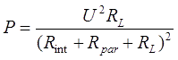 |
(4) |
Dependence of P on RL is well known and depicted on fig.4. It says that maximum of P (i.e. maximum current at fixed supply voltage) is obtained when coil resistance equals the sum of all other resistances of the chain. Consequently, the projectile will be accelerated the best when a gauge and length of the wire are chosen in such a way that its resistance RL = Rint+Rpar.
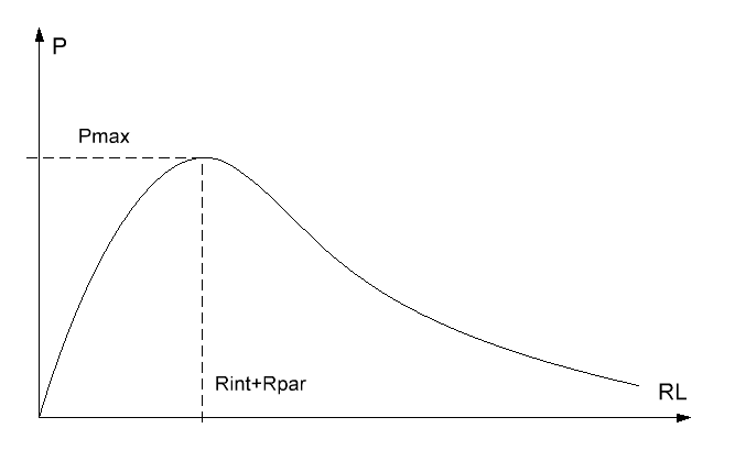 |
Fig. 4. Dependence of power P deposited in a coil on its wire resistance RL. |
At this point P reaches its peak value which is Pmax = U2 / [4·(Rint+Rpar)]. Comparing this equation to formula (3), we have the next relation for the output velocity:
 |
(5) |
3. Assessment of the resistances.
Eq.(5) shows that we must assess limiting values of Rint and Rpar to get an “optimistic“ value of v.
The parasitic chain resistance is treated rather simply – it is determined by on –resistance of the switch, and interconnections. On-resistance of the modern low-voltage MOSFETs is limited not by their chips (which are very low-ohmic), but their leads and makes no more than 5 milliohms (mOhms) as a rule. The same can be suggested for the resistance of the connections (provided they are made of copper buses of enough cross-sections and well-soldered everywhere). In total we get about 10 mOhms ( i. e. one-hundred part of Ohm) for Rpar. Perhaps it is too “overoptimistic” assessment and Rpar in a real construction (especially with long bore demanding prolonged buses) may be higher, but it is OK for our rough calculation.
The situation is much more interesting for the internal resistance of the accu. It seems impossible to fix some unified value of Rint for a huge variety of all types of LiPos. Indeed, their capacity may be in a range from hundreds to thousands mA·h, and voltage ranges from 3,7 V (for 1S-type, i.e. single bank) up to 22,2 V for 6S which means six sequentially connected accus. It is strightforward to suggest that Rint will significantly differ in all that cases.
The way to overcome this difficulty is to introduce some coefficient r which can be called “relative internal resistance” of the accu. Its dimension is Ohm·(mA·h)/V, and a resistance of an arbitrary accumulator will be deduced from r by the following equation:
Rint = r ·U / C (6)
where U,C – battery voltage and capacity, accordingly.
This relation demonstrates that the internal resistance of the battery increases with voltage builds-up and capacity decreases.
The value of r can be determined from the datasheets of different accus, for example, this battery of C = 4000 mA·h has the resistance of about 2,5 mOhm for the individual 3,7 V bank, but, including the interconnections between the elements, it totally gives Rint = 17,9 mOhm for 4-bank battery (4S), so r = 4·10-3 · 4000 / 3,7 ≈ 4 Ohm·(mA·h)/V. That is what we will use for the following calculations.
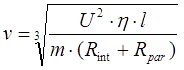
Considering the results obtained, the eq. (5) may be simplified if we suggest the internal accu resistance to dominate (i.e. Rint>>Rpar). Indeed, in the example above the parasitic resistance (which is fixed to 10 mOhms as we said) will be nearly twice lower than Rint which is for 14,8 Volts-battery, while much more voltage (and consequently higher Rint) is used in real constructions. So, Rpar can be suggested negligible for the simplification, and then (5) (accounting for (6)) will transform to
 |
(7) |
4. Calculation of the output velocity.
Fig.5 shows the results obtained from (7) for v when C = 5200 mA·h (which is close to maximum for the elements in stock) and variable voltage. Data for different coilgun calibers (d) from 4 to 10 mm are demonstrated. The length of the projectile of iron considered 4d (and so its mass m was determined). The values of 1S (single bank) to 2x6S (two sequentially connected six-bank accumulators which gives 44,4 V on output) are marked on the voltage scale. Acceleration path (i.e. total length of the windings) is 50 cm. The efficiency was considered equal to the caliber in mm (like I did in previuos calculations), which is close to truth for multistage accelerators.
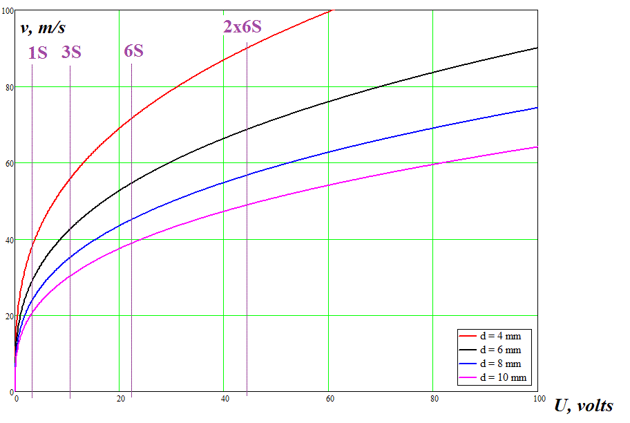
Fig. 5. Maximum speed for multistage ADG calculated according to eq. (7).
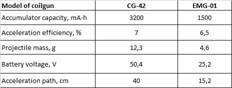
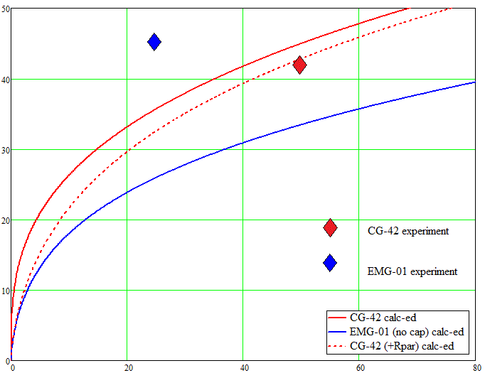
It is interesting to compare the results to the parameters of the really built ADGs. Fig. 6 gives such comparison for two models; CG-42 by J.Murray and EMG-01 form ArcFlashLabs (in fact, that is the same coilgun with the capacitor added between the accu and the coils for the second model). The parameters of the accelerators taken for the calculation (according to the author’s information) are in table 1.
Table 1. Initial parameters of the coilguns for calculation.
To correct the data from simplified eq. (7) for CG-42 coilgun, formula (5) including the parasitic chain resistance Rpar = 10 mOhms was used (which is indicated by the dashed line). Experimental results are depicted by big rhombic symbols.
|
Velocity,
m/s
|
 |
| |
Battery voltage, V |
Fig. 6. Comparison of the experimental and calculative results.
The graphs show that for the case described by (5) (i.e .pure RL-circuit without any caps but with a parasitic resistance) the calculative result coincides with the experiment very well. Contrary, an addition of the capacitive element to the circuit increases the output velocity drastically, and the formulae obtained above become inapplicable.
5. Discussion and conclusion.
What can we say looking at the results?
First, eq. (5) and (6) show a weak (as a cubic root) dependence of v on the initial parameters of the system. I.e., to double the speed, we should increase, for example, voltage in 8 times. This means that improvability of the portable accumulator-driven coilgun is in quite narrow borders.
Secondly, fig. 5 demonstrates that v increases with shrinking of the gauge (which corresponds to my previous assessments of the parameters of accelerators build on other principles). However, the speed of more than 100 m/s for even 4 mm caliber (the least of examined here) is achieved only with 60 V and more battery (which is equivalent to 3 and more sequentially connected 6S accus) – this says about high cost of such a hypothetical construction. Moreover, we must take into account that the number of stages must be extended while the caliber (and hence their length) diminishes to keep a constant acceleration path (4 mm gauge implies more than 30 stages at the path of 50 cm). As each of them is equipped with high-current switch and some minimal control electronics, the constructor of ADG with a competitive parameters must be ready to more expenses than for traditional coilguns (which have already overcome 100 m\s speed limit without any extraordinary engineering tricks).
Thirdly, the parasitic resistance has a substantial influence on the parameters of ADG at voltages low than 20 V. So, for the analyzed-above case of 3200 mA·h capacity the speed lowers doubly for the single-bank accu, and to about 10 % for 6S – type (which corresponds to η ≈ 20 % reducing efficiency) when considering Rpar. This says that the lowest voltage limit of the accumulators for ADG lays somewhere about 20 V and corresponds to 6S-accus.
Finally, the parameters of EMG-01 coilgun show that a capacitor added between power supply and accelerating coils increases the efficiency dramatically by deleting such factor as internal resistance of the accumulator. RL-circuit of ADG turns here to a “traditional” RLC-type with only difference in cap charging directly from the accu (not from a voltage booster, I examined this type of the coilguns here). This fact reveals that conventional capacitor-driven coilguns are still more effective due to lower internal resistance of the capacitors (also called ESR) in comparison to Rint of the LiPo accumulators.
Sincerely Yours,
Eugen.
|