| Home » Articles » Theoretical papers » Coilgun calculations |
On this page, I published the ratios for estimating the maximum projectile velocity achievable in a single-stage Gauss cannon, and it was also promised that in the future similar formulas will be given that generalize these conclusions to the case of multistage coilguns. To do this, first imagine the actual multi-coil accelerator consisting of N sequentially arranged windings (Fig.1). Keeping the designations of the previous articles, we will write down the length of each coil as c, then the total length of the accelerating path will be l = c·N (in fact, in a reality, some separating elements, sensors, etc. should be placed between the windings, but here we will omit such details).
The traditional way of functioning of this system is as follows: each coil turns on at the moment when the accelerated body approaches its front face, and turns off when the projectile reaches some optimal point (in previously accepted designations, this corresponds to the coordinates x1 and x2 of the projectile nose relative to the front face of the coil). Then the next winding is triggered and so on until the projectile flies out of the accelerator barrel. In practice, more complex algorithms can be utilized - for example, not one, but several windings can be turned on simultaneously (then the principle of the so-called "traveling wave" is implemented, which we will definitely talk about in one of the following publications). In this article, without going into these difficulties, we will assume that no more than one coil is operating at any given time, and in all coils the current increases and decreases instantly (as shown here, this corresponds to the most favorable conditions for the acceleration). Under above-stated conditions, kintic energy gain on each stage will be described by eq. (9) from this page, i.e.
where "geometric" function is
and h is form-factor of the coil:
Let's remind that a is ratio of caliber of the winding wire's core to its dia with isolation, δ - resistivity of the wire (δ ≈ 0,0175 Ohm·mm2/m for copper), Внас is saturation flux density of the projectile (Внас ≈ 2 Tl for iron), z - length of the projectile, and P - electric power. Under these conditions, it is obvious that all coils will have the same dimensions and consume the same power P, and the task of optimizing our coilgun is to select their geometric parameters D and c, as well as the length of the projectile z and the on/off coordinates x1 and x2, which, given the values a, P and caliber d, will correspond to the maximum output velocity of the projectile. The increment of kinetic energy, described by the value (1), will be received by the projectile when passing each of the N stages of our accelerator. Since we have agreed that the coils are the same, we will get a classical description of equidistant motion, which will be more reliable the more stages we have (then it is possible to neglect the uneven acceleration of the projectile within a separate coil). In this case, we can use the ratio (14a) for a single-stage system from this page, with the only difference that the acceleration length (read - acquired kinetic energy) increases by N times:
where geometric function
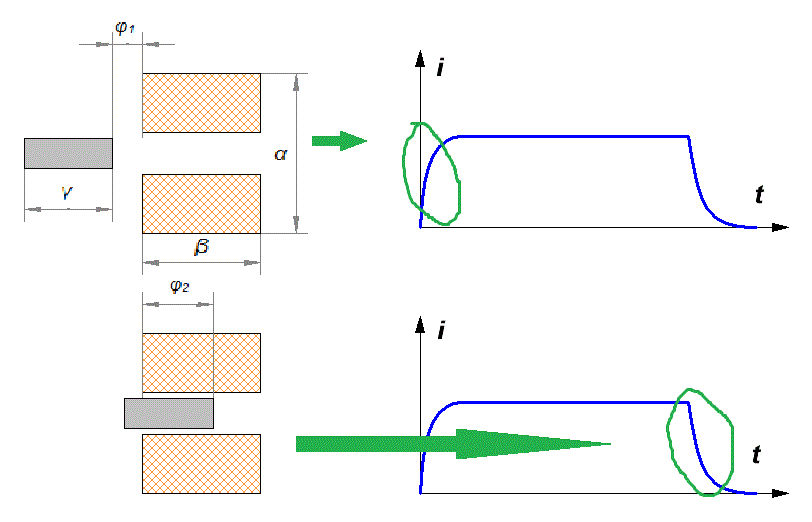
Let me remind you that when considering the optimal parameters of a single-stage system, it turned out that the maximum speed is achieved when the length of the accelerated body z tends to zero and the "ideal" winding shape is chosen (D = 3d, c = 2d). In this case, the acceleration was carried out from an infinite distance from the coil (and lasted, respectively, infinitely long). Obviously, such idealization is impossible in the multistage accelerator of limited dimensions, - we need to consider arbitrary, but finite values of z, x1 and x2 - they should be limited only so that (as we agreed earlier) the active states of neighboring coils don't "overlap", i.e. x1+x2 < c. For the convenience of further consideration, we will translate all geometric parameters into a dimensionless form, expressing them in terms of the accelerator gauge d: D = α·d, c = β·d, z = γ·d, x1 = φ1·d, x2 = - φ2·d (see fig. 2).
Fig. 2. Designations of the geometric parameters.
In addition, we take into account the fact that the active states of the coils can be spaced by coordinate (i.e., each next winding turns on after some time after the previous one is turned off) - in this case, the instantaneous power in formula (3) can be higher than the average one by β/(φ1+φ2) times. As a result, we obtain the ratio for the output speed of a coilgun of length l:
where geometric coeffitient is
and Y is a dimensionless expression of the coil's form-factor (2):
Note that the change in (5) compared to the same ratio for a single-stage accelerator consists only in a change in the numerical coefficient (due to a change in the boundaries of integration in (3)), and in the appearance of a multiplier l/d under the root. However, in this case, it is possible to obtain a speed dependence not on the power of the source (which, generally speaking, can vary in very large ranges), but on the energy capacity of the accelerator E (i.e., on the energy spent on the shot), which is much more useful. To do this, note that in the form (5) we have the following relation for the velocity of the projectile:
where A is some numerical multiplier. Recall that for equidistant motion, the acceleration duration t can be expressed in terms of finite velocity and distance as
Expressing the power as P = E / t and combining the ratios (5') and (7), we obtain :
Substituting all the values from (5) into the numerical multiplier A in (8), we finally get:
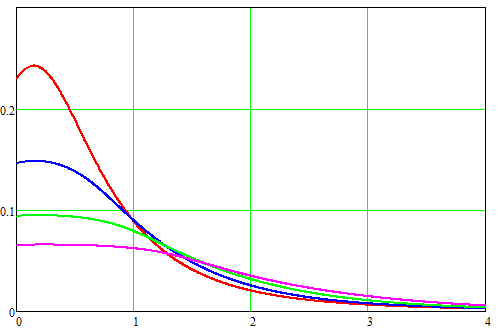
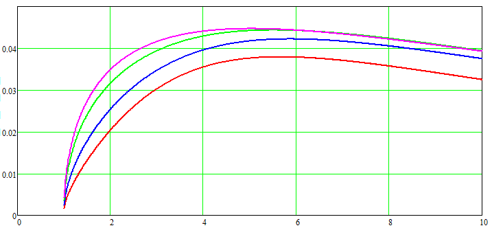
Here, d and l are expressed in centimeters, and the energy spent on accelerating the projectile is in Joules. Formula (9) is a basic ratio that allows us to estimate the velocity of a projectile of arbitrary length accelerated by a chain of coils of total length l, whose geometric parameters and the coordinates of their on/off are described by a geometric multiplier Wf. Figure 3 illustrates the dependences of Wf on some parameters at fixed values of the activation coordinates: φ1 = ½(β-γ), φ2 = ½(γ+β), which corresponds to the activation of each subsequent coil when the projectile is located exactly in the middle of the previous one.
Actually, Wf represents the whole "highlight" of the ratio we have established. If the accelerator is optimized (i.e. the dimensions of the projectile and coils, as well as the time diagrams of their operation are selected correctly), then Wf takes the maximum value. Thus, in order to find the maximum speed achievable in a particular system, it is necessary to determine the maximum value of Wf depending on its parameters. Since there are as many as five of these parameters, it is better to use a computer for this purpose, which I did with the help of the MathCad. As a result, it was found that the absolute maximum of Wf is Wfmax ≈ 0.329, and is achieved at the following parameter values: γ = 0, α = 1.77, β = 0, φ1 = 0.882 φ2 = - 0.066. The accuracy of modeling by variables here is 0.001. Thus, the maximum speed is achieved for an infinitely short projectile and infinitely "flat" coil. Now, finally, we can get the formula for the maximum achievable projectile velocity in a multi-stage accelerator explicitly. Substituting Wf = Wf max ≈ 0.329 into (9), we have:
Let's recall once again the meaning of the parameters included in the formula: a - the dimensionless ratio of the caliber of the winding wire "by copper" to its effective diameter in insulation (usually a = 0.75..0.85 is obtained) Bнас - saturation induction of the projectile material, Tl δ - is the resistivity of the winding conductor, Ohms *mm2/m E - is the electrical energy expended on the shot, J ρ - the density of the projectile material, kg/m3 d - coilgun caliber - inner diameter of coils, cm l - the total length of the accelerating coils, cm. Let's try to estimate the maximum achievable speed in such a system: an accelerator with an energy capacity of E = 500 J, having 10 coils of caliber d = 0.8 cm and a length of 2 cm each, wound with an average density of a = 0.8 with a copper wire (i.e., we consider quite a portable coilgun of medium power). We get vmax ≈ 292 m/s for a projectile made of iron (Bнас = 2 Tl, ρ = 7870 kg/m3), vmax ≈ 326 m/s for a permendur (Bнас = 2.43 Tl, ρ = 8100 kg/m3). For the acceleration efficiency estimates for this example, see below. As can be seen, even for such a very modest in terms of parameters multi-stage gauss gun, the transonic velocities of the projectile are theoretically achievable... Similarly, it is possible to obtain a ratio for efficiency. I will give it without a derivation (an interested reader will be able to repeat the course of my calculations):
As can be seen, in order to maximize efficiency, it is necessary to increase the value of Wf 4/3 ·γ. It has a maximum at γ = 1.93, α = 2.41, β = 0, φ1 = 0.777, φ2 = 0.615. At such values, for the example given above, the iron core will be accelerated with a maximum efficiency of 17.1% (which corresponds to a speed of 184 m/s), and the permendure one - 20.9% (v = 205 m/s).
Formulas (9) - (11) are extremely useful, because they allow us to estimate the maximum achievable characteristics of a multi-stage accelerator according to its design parameters, as well as to check how their variation affects the final properties of the gauss gun. What can be concluded from the form of these relations? Firstly, it is obvious that the key characteristic of a multi-coil electromagnetic accelerator is its caliber. The efficiency is directly proportional to d, and the velocity of the projectile is inversely proportional (interestingly, this corresponds well to the empirical assumption η ≈ d, which I used when writing previous articles about the properties of accelerators of various configurations). This feature distinguishes the multi-stage system from a single-stage one - where the dependence of the output speed on the caliber was much weaker. Second: the saturation induction of the accelerated body material, and the value of the winding density a (read - the quality of manufacture of accelerating coils) are also quite significant parameters. Finally, the length of the accelerator and its energy capacity (that is, the characteristics that are most amenable to change by a designer) are, unfortunately, the least significant for increasing the velocity of the projectile - it depends on them only as a cubic root. That is, in order to increase the speed by 2 times while maintaining all other parameters, it is necessary to increase either the length of the accelerator or the energy consumed by 8 times. The resistivity of the wire is equally insignificant - it follows that winding of coils with an aluminum or silver conductor instead of the usual copper one which is sometimes proposed will affect the acceleration of the projectile very weakly.
Sincerely Yours, Notes: 1. The calculation of the geometric multiplier Wf can be simplified if you fix any variable that is part of it (for example, set a specific length of the projectile and /or accelerating coil). In addition, its appearance can be generalized to the case of projectiles whose shape differs from cylindrical. For example, for a spherical body, you can use the dependencies given here. 2. From the discussion of the last two formulas, it can be seen that the set of geometric parameters corresponding to the maximum efficiency is very different from that for maximum speed - this once again emphasizes that increasing the efficiency and speed of the coilun's projectile are completely different tasks. 3. The efficiency estimates according to eq. (11) should be treated with caution, since it is obtained based on certain approximations that are valid only for systems with deeply saturated ferromagnet. In our case, this means that formula (11) will be the more accurate the higher the accelerator energy and the smaller its caliber. According to estimates, reasonable values are obtained at energy levels of at least several dozen joules and a caliber of up to 2..3 centimeters. 5. When using ratios (9) - (11) to estimate the limiting parameters of real systems, it should be remembered that previously we took d equal to both the inner diameter of the coils (accelerator caliber) and the outer diameter of the projectile (i.e., a barrel with zero wall thickness was assumed). In practice, of course, the diameter of the accelerated body will be noticeably smaller than d. As shown here, this will not lead to a change in its speed, but should reduce the efficiency of the coilgun.
| |||||||||||||||||||||||||||||||
| Views: 779 | | | |||||||||||||||||||||||||||||||
| Total comments: 0 | |


